ESC1

Exigo System Controller
- Control and routing of audio channels
- 115 - 230 VAC primary power and 24 - 48 VDC secondary power
- Redundant Ethernet connections
- Digital audio processing
- Receives, handles and stores fault messages from the system
- Interface to PABX and iPBX
- Interface to telecom management, safety, automation and security systems
- Voice message storage
- Programmable alarm generator
- Tick tone generator
The Exigo System Controller is designed for use in marine/offshore and onshore environments. The construction is extremely robust and can handle mobile environments as well as stationary, temperature controlled rooms. The system controller is based on IP technology, giving it extreme flexibility, superb audio quality and huge integration possibilities.
The system controller handles routing and prioritization of up to 32 simultaneous audio channels in the system. The audio can be distributed from up to 150 audio inputs to up to 250 zones.
The system controller features a display where status and faults can be viewed. This display also allows configuration of simple parameters. The system controller monitors and receives status information from every component in the system. Faults are time stamped, and presented in chronological order on the display. Buttons allow an operator to acknowledge and reset faults. The network connection to every component in the system is monitored, so a defect switch or broken cable will be detected just as reliably and fast as any other fault in the system.
The system controller also acts as the system’s alarm generator and audio message storage. The embedded alarm generator features a set of the most common alarm tones, but can also be programmed to support custom alarm tones and patterns. Stored voice and audio messages are easily uploaded to the system controller as standard .wav files.
The system controller’s control inputs/outputs and audio inputs can be used locally by the system controller (e.g. for PTT and audio from a handheld microphone) or can be controlled by the system (e.g. audio input for background music).
Contents
- 1 Installation
- 1.1 Overview - Front
- 1.2 Overview - Back
- 1.3 Overview - Internal
- 1.4 Placement
- 1.5 Mounting
- 1.6 Power Supply
- 1.7 Grounding
- 1.8 Installing Primary System Controller Board
- 1.9 Ethernet Connections
- 1.10 Serial Port Connections to PSC
- 1.11 Fault Relay
- 1.12 Control Inputs
- 1.13 Control Outputs
- 1.14 Audio Inputs
- 2 Optional Audio Inputs/Outputs
- 3 Dimensions
- 4 Accessories
- 5 Additional Documentation
Installation
Overview - Front

| 1 | Mounting Flange | The mounting flanges are used to mount the unit in 19” equipment racks |
| 2 | Ventilation Inlets | The ventilation inlets should be kept free of obstacles and dust. Fans control the airflow based on internal temperature |
| 3 | Headphone Jack | Headphones can be connected for listening to the different audio streams in the system |
| 4 | Status Indicators | The status indicators are used to display the status of important parameters such as power supplies and faults |
| 5 | LCD Display | The LCD screen displays status and a graphical user interface |
| 6 | Control Knob | The control knob is used to select and execute menu items in the user interface. The knob can be rotated and pressed. |
| 7 | Front Cover | The front cover can be opened in order to gain access to the primary system controller board and the optional function board slot |
| 8 | Cover Screws | The two cover screws secure the front cover in place. To open the front cover, these two screws must be loosened and pulled out 1.5 – 2 cm. The screws can then be used as handles to pull out the front cover |
| 9 | Integrated Handle | These integrated handles make it easy to maneuver the unit, without adding to the installation depth |
Overview - Back

| 1 | Ethernet Ports | Redundant Ethernet connections for audio and control data |
| 2 | Serial Ports | RS-232 for console and RS-232/422/485 for integration with other equipment |
| 3 | Control Inputs | Six configurable control inputs that can be optionally monitored. Each input is activated by closing the loop between the two terminals |
| 4 | Fault Relay Output | A switching relay (NO, NC & COM) is used to indicate faults in the system |
| 5 | Control Outputs | Six configurable control outputs. Each is made of a switching relay (NO, NC and COM) in parallel with a 24VDC signal. The 24VDC part of the control output can source max 200mA and has overcurrent protection. |
| 6 | Audio Input | Microphone and line-in audio inputs for microphones or external audio sources |
| 7 | Audio Output | One configurable audio output which can be used for analog integration |
| 8 | Optional Audio I/O | Analog audio inputs available in the system if the optional AGA board is inserted in the ESC1 |
| 9 | Ground Connection | Ground connection for grounding of the unit. This is connected in parallel with the ground connection in the AC power inlet |
| 10 | DC Power Inlet | DC power inlet for 24 to 48 VDC |
| 11 | AC Power Switch | Power switch for AC power. This switch will not turn off the system controller if DC backup is connected |
| 12 | AC Power Inlet | AC power inlet for 110 to 230 VAC. The power inlet has a V-Lock mechanism for a secure connection |
Overview - Internal

| 1 | Feature Board slot | Slot for an optional AGA board for 12 additional analog inputs |
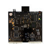
| 2 | PSC slot | Slot for the primary system controller board (AMC-IP Card) |
| 3 | PSC Hotswap | |
| 4 | PSC Eth0 | |
| 5 | Status indicators | Local status indicators for the primary system controller board |
| 6 | Hotswap | |
| 7 | Primary System Controller | Primary System Controller board for the ESC1 |
| 8 | STIC (SIM card) | Stentofon Identity Card containing the ESC1’s MAC address and basic settings. |
| 9 | SSC Serial Connector | |
| 10 | Battery | Battery for the time clock |
Placement
The ESC1 can be located anywhere in the equipment rack. It is however advisable to install it at eye-level as this will make it easier to operate the user interface on the display.
Mounting
The ESC1’s mechanical construction is rigid enough to be mounted using only the four holes in the mounting flange to secure it to the rack. It is however considered good practice to mount support rails if the system is installed in a moving environment.
Power Supply
The ESC1 shall be connected to the equipment rack’s primary and secondary (emergency) source of power.
The requirements for the power rails are listed in Table 3. The cables used for power shall be dimensioned accordingly to the voltage and current consumption of the ESC1.
 Only one power source may be connected if the power source itself is redundant
(e.g. UPS) or if the class/installation permits a single source of power.
 Only one power source may be connected if the power source itself is redundant
          (e.g. UPS) or if the class/installation permits a single source of power.
 Both power inputs are equipped with a lock, preventing the plug from falling out.
Make sure that the plug is properly inserted, and that the lock is engaged.
 Both power inputs are equipped with a lock, preventing the plug from falling out.
          Make sure that the plug is properly inserted, and that the lock is engaged.

Grounding
It is always good practice to ground the cabinet of equipment installed in racks. This ensures safety and good EMC.
If the unit is powered entirely through the DC power inlet, the ground connection is the only way to connect the ESC1 to ground. The grounding connection of the ESC1 should be connected to the equipment rack’s ground strip using a ground wire of at least 0.75 mm² (AWG 19).
Installing Primary System Controller Board
The primary system controller (PSC) or AMC-IP board must be inserted into the system controller. Before inserting the PSC board into the system controller, the SIM card containing the MAC address and basic settings must be inserted into the board. The SIM card shall be mounted in the socket located in the lower corner of the board (See Figure 10) by sliding the metal retention clip back and flipping the lid open (the lid itself comprises the socket). The SIM card itself shall then be inserted into the socket before closing it and the retention clip fastened.
To install the PSC board, the front cover must be opened by unscrewing the two front cover retention screws. Open the front cover by pulling it out (using the two loosened screws as handles) and flipping it down. The PSC board shall be inserted in the lowest position.
 Disconnect all power from the ESC1 before installing or removing the PSC board
Configuration data for all units in the system is stored in nonvolatile memory on the PSC board
Ethernet Connections
The ESC1 shall be connected to the network using one or two Ethernet cables, depending on the system interconnection scheme.
Note that this device does not support RSTP.
Serial Port Connections to PSC
The ESC1 is equipped with two serial ports on the PSC board, which can be used for external equipment integration. Serial port 0 offers RS232 only and is most commonly used for console access. Serial port 1 can be configured as either RS232 or RS422.
The baud rate for both ports is configurable through software.

| 1 | Pin 1 - Not used | 9 | Pin 1 - RS422 Tx+ | |
| 2 | Pin 2 - Not used | 10 | Pin 2 - RS422 Tx- | |
| 3 | Pin 3 - RS232 Tx | 11 | Pin 3 - RS232 Rx | |
| 4 | Pin 4 - GND | 12 | Pin 4 - GND | |
| 5 | Pin 5 - GND | 13 | Pin 5 - GND | |
| 6 | Pin 6 - RS232 Rx | 14 | Pin 6 - RS232 Tx | |
| 7 | Pin 7 - Not used | 15 | Pin 7 - RS232 Rx+ | |
| 8 | Pin 8 - Not used | 16 | Pin 8 - RS232 Rx- |
The selection between RS232 and RS422 on serial port 1 is done with a DIP-switch (S601) located on the system controller’s primary system controller board (see picture below).
When switch number 8 is set in the off-position, RS232 is selected (default). If the same switch is set in the on-position, RS422 is selected.
The primary system controller board is accessible when opening the system controller’s front cover. The board must be pulled out and removed in order to access the DIP-switch.
Disconnect all power from the ESC1 before pulling out the primary system controller board.

| 1 | Switch 1 | Console |
| 2 | Switch 8 | Serial 1 Protocol |
The image above shows the system setting switch on the primary system controller board. Switch number one is used to turn the Linux console on and off.
If serial port 0 is used for any integration, this switch must be set to off in order to disable the Linux console messages on the serial port. Switch number 8 is used to control the protocol used for serial port 1.
 All other switches shall be left in the default positions. Changing the positions
          of these switches will lead to unstable operation of the entire system
Fault Relay
The ESC1’s fault relay will trigger whenever a fault is present in the system. The relay is kept in the NO position if there are no faults in the system. If any fault is generated, the relay will fall to the NC position. This ensures that the fault relay will fall to its fault position in case of a power failure. The connection to external equipment should be made according to the external equipment’s requirements.
- No fault in system = Relay in NO position.
- Fault in system = Relay in NC position.
The fault relay should be routed from the ESC1 output to a terminal block in the equipment rack.
Control Inputs
The Control Inputs should be routed from the ESC1 screw terminal to terminal blocks in the equipment rack. The number of inputs used depends on the specific system.
Control Outputs
The Control Outputs on the ESC1 should be routed to terminal blocks in accordance with the specific system’s needs. Cable diameter used is max 0,25 mm² flexible.
Audio Inputs
The two audio inputs on the ESC1 can be used for background music, external alarms or local microphone. The audio inputs should be routed to terminal blocks in the equipment rack or local audio sources as required by the specific system.
Optional Audio Inputs/Outputs
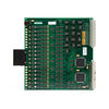
In systems where several analog audio inputs and/or outputs are required, the most cost optimal solution may be to use the AGA Board in the ESC1.
By adding this board, 12 configurable audio inputs/outputs become available on the ESC1. These I/Os can be used as inputs on the same line as the permanent line input, and as outputs to external systems (e.g. radio systems).
The AGA board must be installed in the optional feature board slot of the ESC1. This slot is accessed by opening the ESC1’s front cover, and is located above the primary system controller board.
Disconnect all power from the ESC1 before installing or removing the AGA board.
The input/output levels on the optional audio lines can be adjusted with the potentiometers at the front of the AGA board.
These potentiometers are shown in picture below. There are 16 potentiometers, but only the first 12 (counting from left in the figure) are used.

| 1 | Potentiometers |
| 2 | AGA Board |

| 1 | Audio I/O Line 1 |
| 2 | Audio I/O Line 2 |
| 3 | Audio I/O Line 3 |
| 4 | Audio I/O Line 4 |
| 5 | Audio I/O Line 5 |
| 6 | Audio I/O Line 6 |
| 7 | Audio I/O Line 7 |
| 8 | Audio I/O Line 8 |
| 9 | Audio I/O Line 9 |
| 10 | Audio I/O Line 10 |
| 11 | Audio I/O Line 11 |
| 12 | Audio I/O Line 12 |
The different audio sources and/or destinations must be connected to the ESC1 according to picture abowe. The lines are transformer coupled and polarity is of no importance.
The direction (input/output) of each individual audio line is configured from the Exigo Management Tool.

Dimensions

Accessories
|
|
|
|---|---|---|
| AMC-IP | AGA Board | EPMS100 |
Additional Documentation
For more documentation, please visit the Zenitel web page: https://www.zenitel.com/product/esc1