EAPIR-8

EXIGO alarm panel
- Network call panel for console mounting
- Compatible with AlphaCom and Exigo systems
- Eight programmable buttons with individual labels and status indicators
- Communication and power over Ethernet
- Optional button protection covers
- Indicators for power, call and fault
- For single or dual systems (A and B systems)
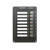
The EAPIR-8 alarm panel is developed for console mounting. The alarm panel features eight fully programmable buttons, which can be used to manually initiate fire alarms, gas alarms or any other action in the Exigo system. The alarm panel features indicators to show the status of the power supply, if an alarm is active and whether a fault is present in the system. The alarm panel’s buttons features two independent status indicators each, which can be used to show the status of the related button’s function. The alarm panel is fully digital, and connects to the Exigo system over standard Ethernet. Two Ethernet ports are available in order to facilitate redundant cabling and connection to A and B system. The alarm panel is fully monitored to ensure detection of any fault which may compromise the system’s functionality.
Contents
Installation
Overview - Front

| 1 | Status indicators | Indicates status for power, system and activity |
| 2 | Backlight control | Button to adjust backlight of labels, buttons and indicators |
| 3 | Screw hole | 4 holes used to mount the panel |
| 4 | Label window | Label insertion slot 1 |
| 5 | Button protection | |
| 6 | Function indicators | |
| 7 | Function button |
Overview - Back

| 1 | I/O interface | Interface for control inputs, control outputs and analog audio |
| 2 | Ethernet port 1 | Ethernet port number 1 |
| 3 | Ethernet port 2 | Ethernet port number 2 |
| 4 | Button expansion | Connection for the first button expansion module, a white connector on top and an empty “slot” below |
| 5 | Signal relay | Programmable relay. Max: 250VAC/220VDC, 2A, 60W |
| 6 | External audio | Connection for microphone and optional external loudspeaker |
| 7 | Local power | Local input for 24VDC power supply |
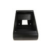
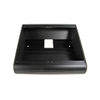
Placement
The ECPIR and EAPIR panels can be flush-mounted in a console or put into a back-box. The back-box can be placed on a surface or mounted on the wall.
 The back-box is not part of the panel and must be ordered separately.
Console Mounting
When mounted in a console, a cut-out must be made for the panel, or group of panels. Please refer to the panel’s dimensional drawing for making cut-outs.
Back-box Mounting
Two different back-box options are available for the ECPIR and EAPIR panels: EMBR-1 and EMBR-2.
Power Supply
The access panels shall be powered as dictated by the requirements for the class or installation. In an A-B configuration, power shall be provided from both systems in one of the following arrangements.
PoE + Local Power
PoE is provided from one of the systems through the Ethernet connection. The other system must provide a DC current in a separate cable, in addition to the Ethernet cable. The DC current may
also be provided locally, as long as this is provided by a different power connection than the PoE system. See the figure above for the location of the 24VDC local power inlet on the panel.
 PoE cannot be supplied from both systems as this will lead to a reset of the panel during a switchover
Spare-Pair Power To provide redundant power to the panels, use spare-pair powering by utilizing the EPIPR-6 power injector. In this configuration, power is delivered from both systems continuously, through the two spare-pairs in the Ethernet connection. Please observe grounding considerations. PSUs in either rack should have floating supply to avoid ground loops.
Ethernet
The access panels shall be connected to the central equipment as dictated by the requirements for the class or installation.
In an A-B configuration, Ethernet shall be connected to both systems, through separate cables routed through separate fire zones. Network equipment must support RSTP for A-B configuration.
Inputs and Outputs
The access panels are equipped with control inputs and control outputs. These 6 inputs/outputs can be used in the system in the same way as the control inputs/outputs on the central equipment. These inputs/outputs must be configured to be either an input or an output; hence there are in total 6 inputs, outputs or a combination of these. The inputs on the access panels are not monitored, and should therefore only be used for non-critical applications. The access panels also include two separate relays, which can be used for a multitude of applications, e.g. muting of local loudspeakers.
Signal Relays
Two signal relays that are configurable like a Control Outputs from EMT.
Connections

Expansion Module
The EAPIR-8 can connect up to 4 Expansion Modules EBMDR-8, giving maximum 40 programmable buttons.

Restore Factory Defaults
Dimensions

Accessories
|
|
|
|---|---|---|
| EBMDR-8 | EMBR-1 | EMBR-2 |
Additional Documentation
For more documentation, please visit the Zenitel web page: https://www.zenitel.com/product/eapir-8