Difference between revisions of "EN 54"
(→System Fault) |
|||
| (56 intermediate revisions by the same user not shown) | |||
| Line 1: | Line 1: | ||
| − | This article describes the different precautions that needs to be considered when using Exigo where EN 54 is applicable.<br> | + | [[File:EN 54 product label.JPG|thumb|right|450px|EN54 label]] |
| − | Exigo is tested and certified according to | + | This article describes some of the different precautions that needs to be considered when using Exigo where EN 54 is applicable.<br> |
| + | Exigo is tested and certified according to EN54-16: Fire detection and fire alarm systems.<br> | ||
| + | In order to comply with the strict rules of EN54 there are some additional equipment needed: | ||
| + | {| class="wikitable" | ||
| + | !Item no: | ||
| + | !Short code: | ||
| + | !Description: | ||
| + | |- | ||
| + | |102 3598 000 | ||
| + | | | ||
| + | |Exigo Overvoltage Protection 2x 100V/70V lines (1 per ENA2200) | ||
| + | |- | ||
| + | |102 3598 100 | ||
| + | | | ||
| + | |Exigo Overvoltage Protection 3x I/O lines | ||
| + | |- | ||
| + | |N/A | ||
| + | | | ||
| + | |Bourns 1250-2S-230 (surge protection - 230VAC) | ||
| + | |- | ||
| + | |N/A | ||
| + | | | ||
| + | |Bourns 1320-S-48 (surge protection - 48VDC) | ||
| + | |- | ||
| + | |300 5010 176 | ||
| + | |SPA-REL-V2 | ||
| + | |Multipurpose potential free relay contact | ||
| + | |} | ||
| + | == Exigo Overvoltage Protection 2x 100V/70V lines == | ||
| + | In order to comply with the strict rules of EN54 it is mandatory to use overvoltage protection on the speaker lines.<br> | ||
| + | [[File:EN 54 overvoltage protection 1.JPG|thumb|left|700px|Overvoltage Protection Speaker Line]] | ||
| + | <br style="clear:both;" /> | ||
| + | The diagram shows how the overvoltage protection ('''F21''') is wired. | ||
| + | == Exigo Overvoltage Protection 3x I/O lines == | ||
| + | In order to comply with the strict rules of EN54 it is mandatory to use overvoltage protection when interfacing with external system using the control input(s).<br> | ||
| + | [[File:EN 54 overvoltage protection 2.JPG|thumb|left|700px|Overvoltage Protection Control Inputs]] | ||
| + | <br style="clear:both;" /> | ||
| + | The diagram show an example on overvoltage protection ('''F20''') on the control inputs: | ||
| + | * Control inputs 1 and 2 are local buttons located inside the rack. These do not need protections since they are not interfacing to any external system. | ||
| + | * Control inputs 3, 4 and 5 are interface to the fire alarm system. They need to have overvoltage protection since they are interfacing external systems. | ||
| + | == Surge Protection - 230VAC == | ||
| + | In order to comply with the strict rules of EN54 it is mandatory to use surge protection on the 230VAC. | ||
| + | [[File:EN 54 surge protection 230.JPG|thumb|left|700px|Surge Protection 230VAC]] | ||
| + | <br style="clear:both;" /> | ||
| + | |||
| + | The diagram shows an example on how to wire the surge protection ('''F10''').<br> | ||
| + | The surge protection are connected to the AC Main input. This way the battery charger, ESC1 Controller and ENA2200 amplifier will all be protected by the surge protection ('''F10'''). | ||
| + | |||
| + | == Surge Protection - 48VDC == | ||
| + | In order to comply with the strict rules of EN54 it is mandatory to use surge protection for the [[ENSER-8]] switch and the [[IEM-3000-4PC]] PoE module (48VDC). | ||
| + | |||
| + | [[File:EN 54 surge protection DC.JPG|thumb|left|700px|Surge Protection for the ENSER-8 and the IEM-3000-4PC PoE module]] | ||
| + | <br style="clear:both;" /> | ||
| + | |||
| + | The diagram show an example on how to wire the surge protection ('''F11''').<br> | ||
| + | The [[ENSER-8]] switch and the [[IEM-3000-4PC]] PoE module gets power from the same output on the battery charger.<br> | ||
| + | The surge protection is connected to the same output and will protect both the [[ENSER-8]] switch and the [[IEM-3000-4PC]] PoE module. | ||
| + | |||
| + | == SPA-REL-V2 == | ||
| + | In order to comply with the strict rules of EN54 it is mandatory to use SPA-REL-V2 on the control outputs. | ||
| + | |||
| + | [[File:SPA-REL-V2 wiring example.JPG|thumb|left|700px|SPA-REL-V2 wiring example]] | ||
| + | <br style="clear:both;" /> | ||
| + | The diagram show an example on how to wire the SPA-REL-V2 ('''R1, R2 and R3''').<br> | ||
| + | The control output 1, 2 and 3 on the ESC1 controller are protected by individual SPA-REL-V2.<br> | ||
| + | It is also recommended to use SPA-REL-V2 even if the installation is not EN54. | ||
| + | |||
| + | == System Fault == | ||
| + | In order to comply with the strict rules of EN54 it is mandatory to have system fault visibly indicated.<br> | ||
| + | From EN54-16:<br> | ||
| + | '''''8.5 System fault'''''<br> | ||
| + | ''a) a system fault shall be visibly indicated by means of the general fault warning indicator '''and a separate light emitting indicator on the VACIE'''.'' <br> | ||
| + | |||
| + | This is achieved by using a control output and a external LED for indication of system fault on the ESC1. | ||
| + | |||
| + | [[File:EN 54 system fault 1.JPG|thumb|left|700px|System Fault LED]] | ||
| + | <br style="clear:both;" /> | ||
| + | |||
| + | To program a fault indication on a control output:<br> | ||
| + | Go to '''Components view''' > '''[[:Category:Output Actions | Output Actions]]'''<br> | ||
| + | Drag '''[[Fault Indication]]''' to the desired [[Control Outputs | Control Output]]. | ||
| + | |||
| + | [[File:EN 54 system fault 2.JPG|thumb|left|500px|System Fault - control output programming]] | ||
| + | <br style="clear:both;" /> | ||
| + | |||
| + | Set the following parameters: | ||
| + | * Subscribe to: Faults | ||
| + | * Filter Mode: Devices | ||
| + | * Affected Devices: ESC1 A | ||
| + | * System Message: Software fault | ||
| + | |||
| + | == Complete list of Exigo EN54 equipment == | ||
| + | This is a complete list of all Exigo equipment in the EN54-16 Certificate: | ||
| + | |||
| + | {| class="wikitable" | ||
| + | !Item no: | ||
| + | !Short code: | ||
| + | !Description: | ||
| + | |- | ||
| + | |102 3000 100 | ||
| + | |ESC1 | ||
| + | |Exigo System Controller | ||
| + | |- | ||
| + | |102 3102 200 | ||
| + | |ENA2200 | ||
| + | |Exigo Network Amplifier 2 x 200W | ||
| + | |- | ||
| + | |102 3200 030 | ||
| + | |ECPIR-P | ||
| + | |Exigo Call Panel, PTT Button | ||
| + | |- | ||
| + | |102 3200 033 | ||
| + | |ECPIR-3P | ||
| + | |Exigo Call Panel, PTT Button and 3 buttons | ||
| + | |- | ||
| + | |102 3253 008 | ||
| + | |EBMDR-8 | ||
| + | |Exigo Button Expansion Module, 8 Buttons | ||
| + | |- | ||
| + | |102 3201 201 | ||
| + | |EAPII-1 | ||
| + | |Exigo Industrial Access Panel, 1 Button | ||
| + | |- | ||
| + | |102 3201 206 | ||
| + | |EAPII-6 | ||
| + | |Exigo Industrial Access Panel, 6 Buttons | ||
| + | |- | ||
| + | |102 3533 011 | ||
| + | |EMMAR-1H | ||
| + | |Handheld Microphone for Exigo ECPIR Indoor Access Panels | ||
| + | |- | ||
| + | |102 3533 312 | ||
| + | |EMMAI-2H | ||
| + | |Handheld Compact Industrial Microphone For Exigo/Turbine | ||
| + | |- | ||
| + | |300 5020 033 | ||
| + | |MB-30G | ||
| + | |Gooseneck Microphone | ||
| + | |- | ||
| + | !colspan="3"|Network | ||
| + | |- | ||
| + | |222 0012 503 | ||
| + | |IE-3000-8TC | ||
| + | |Cisco IE-3000-8TC Switch | ||
| + | |- | ||
| + | |2220012508 | ||
| + | |IEM-3000-4PC | ||
| + | |Cisco IEM-3000-4PC Expansion PoE/PoE+ module | ||
| + | |- | ||
| + | !colspan="3"|Protection | ||
| + | |- | ||
| + | |102 3598 000 | ||
| + | | | ||
| + | |Exigo Overvoltage Protection 2x 100V/70V lines (1 per ENA2200) | ||
| + | |- | ||
| + | |102 3598 100 | ||
| + | | | ||
| + | |Exigo Overvoltage Protection 3x I/O lines | ||
| + | |- | ||
| + | |N/A | ||
| + | | | ||
| + | |Bourns 1250-2S-230 (surge protection - 230VAC) | ||
| + | |- | ||
| + | |N/A | ||
| + | | | ||
| + | |Bourns 1320-S-48 (surge protection - 48VDC) | ||
| + | |- | ||
| + | !colspan="3"|Relay Board | ||
| + | |- | ||
| + | |300 5010 176 | ||
| + | |SPA-REL-V2 | ||
| + | |Multipurpose potential free relay contact | ||
| + | |} | ||
| + | |||
| + | == Optional Functions == | ||
| + | Not all requirements in EN54-16 is mandatory.<br> | ||
| + | The following list are the optional functions that have been tested and certified for Exigo: | ||
| + | |||
| + | {| class="wikitable" | ||
| + | !Point no: | ||
| + | !Optional Function: | ||
| + | |- | ||
| + | |7.6.2 | ||
| + | |Manual silencing of the voice alarm condition. | ||
| + | |- | ||
| + | |7.7.2 | ||
| + | |Manual reset of the voice alarm condition. | ||
| + | |- | ||
| + | |7.9 | ||
| + | |Voice alarm condition output. | ||
| + | |- | ||
| + | |8.4 | ||
| + | |Indication of faults related to voice alarm zones. | ||
| + | |- | ||
| + | |9 | ||
| + | |Disablement condition. | ||
| + | |- | ||
| + | |10 | ||
| + | |Voice alarm manual control. | ||
| + | |- | ||
| + | |12 | ||
| + | |Emergency microphone(s). | ||
| + | |- | ||
| + | |} | ||
| + | Please note that all other optional functions in EN54-16 has not been tested and are not certified for Exigo. | ||
== [[Manuals | Documentation]] == | == [[Manuals | Documentation]] == | ||
| + | All manuals for Exigo can be found [[Manuals | '''here''']].<br> | ||
| + | Manuals/Certification related to EN 54: | ||
| + | * [https://www.zenitel.com/file/6105/download Exigo VACIE EN54 Manual] | ||
| + | * [https://www.zenitel.com/file/5354/download Exigo EN54-16 Certificate] | ||
Latest revision as of 14:56, 8 May 2018
This article describes some of the different precautions that needs to be considered when using Exigo where EN 54 is applicable.
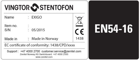
Exigo is tested and certified according to EN54-16: Fire detection and fire alarm systems.
In order to comply with the strict rules of EN54 there are some additional equipment needed:
| Item no: | Short code: | Description: |
|---|---|---|
| 102 3598 000 | Exigo Overvoltage Protection 2x 100V/70V lines (1 per ENA2200) | |
| 102 3598 100 | Exigo Overvoltage Protection 3x I/O lines | |
| N/A | Bourns 1250-2S-230 (surge protection - 230VAC) | |
| N/A | Bourns 1320-S-48 (surge protection - 48VDC) | |
| 300 5010 176 | SPA-REL-V2 | Multipurpose potential free relay contact |
Contents
Exigo Overvoltage Protection 2x 100V/70V lines
In order to comply with the strict rules of EN54 it is mandatory to use overvoltage protection on the speaker lines.
The diagram shows how the overvoltage protection (F21) is wired.
Exigo Overvoltage Protection 3x I/O lines
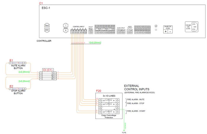
In order to comply with the strict rules of EN54 it is mandatory to use overvoltage protection when interfacing with external system using the control input(s).
The diagram show an example on overvoltage protection (F20) on the control inputs:
- Control inputs 1 and 2 are local buttons located inside the rack. These do not need protections since they are not interfacing to any external system.
- Control inputs 3, 4 and 5 are interface to the fire alarm system. They need to have overvoltage protection since they are interfacing external systems.
Surge Protection - 230VAC
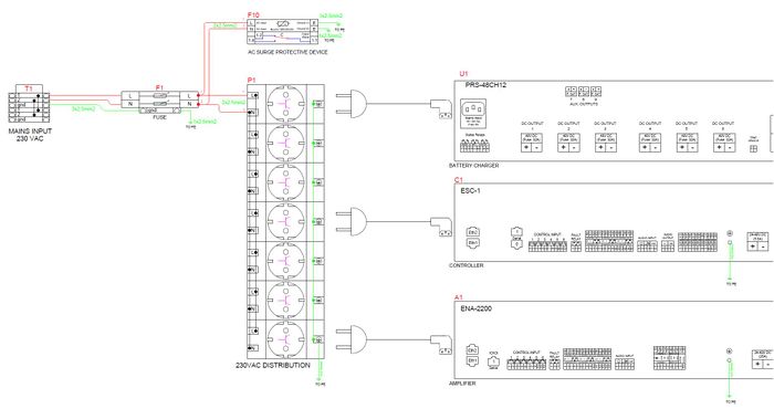
In order to comply with the strict rules of EN54 it is mandatory to use surge protection on the 230VAC.
The diagram shows an example on how to wire the surge protection (F10).
The surge protection are connected to the AC Main input. This way the battery charger, ESC1 Controller and ENA2200 amplifier will all be protected by the surge protection (F10).
Surge Protection - 48VDC
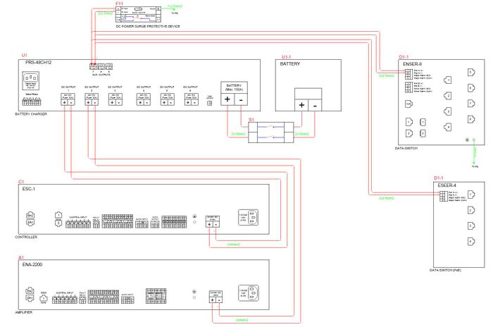
In order to comply with the strict rules of EN54 it is mandatory to use surge protection for the ENSER-8 switch and the IEM-3000-4PC PoE module (48VDC).
The diagram show an example on how to wire the surge protection (F11).
The ENSER-8 switch and the IEM-3000-4PC PoE module gets power from the same output on the battery charger.
The surge protection is connected to the same output and will protect both the ENSER-8 switch and the IEM-3000-4PC PoE module.
SPA-REL-V2
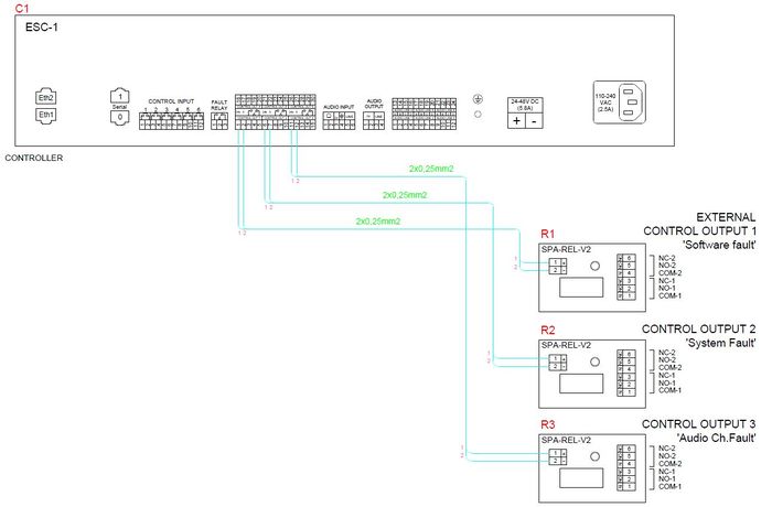
In order to comply with the strict rules of EN54 it is mandatory to use SPA-REL-V2 on the control outputs.
The diagram show an example on how to wire the SPA-REL-V2 (R1, R2 and R3).
The control output 1, 2 and 3 on the ESC1 controller are protected by individual SPA-REL-V2.
It is also recommended to use SPA-REL-V2 even if the installation is not EN54.
System Fault
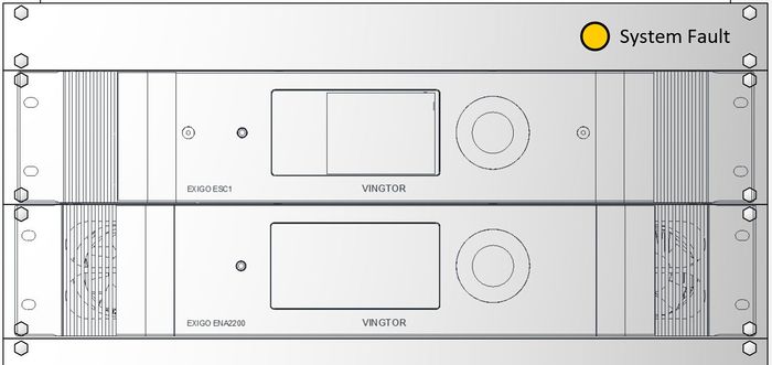
In order to comply with the strict rules of EN54 it is mandatory to have system fault visibly indicated.
From EN54-16:
8.5 System fault
a) a system fault shall be visibly indicated by means of the general fault warning indicator and a separate light emitting indicator on the VACIE.
This is achieved by using a control output and a external LED for indication of system fault on the ESC1.
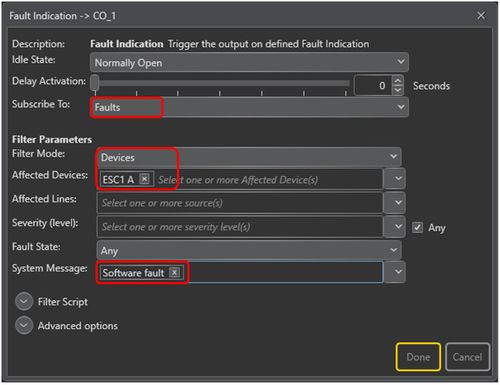
To program a fault indication on a control output:
Go to Components view > Output Actions
Drag Fault Indication to the desired Control Output.
Set the following parameters:
- Subscribe to: Faults
- Filter Mode: Devices
- Affected Devices: ESC1 A
- System Message: Software fault
Complete list of Exigo EN54 equipment
This is a complete list of all Exigo equipment in the EN54-16 Certificate:
| Item no: | Short code: | Description: |
|---|---|---|
| 102 3000 100 | ESC1 | Exigo System Controller |
| 102 3102 200 | ENA2200 | Exigo Network Amplifier 2 x 200W |
| 102 3200 030 | ECPIR-P | Exigo Call Panel, PTT Button |
| 102 3200 033 | ECPIR-3P | Exigo Call Panel, PTT Button and 3 buttons |
| 102 3253 008 | EBMDR-8 | Exigo Button Expansion Module, 8 Buttons |
| 102 3201 201 | EAPII-1 | Exigo Industrial Access Panel, 1 Button |
| 102 3201 206 | EAPII-6 | Exigo Industrial Access Panel, 6 Buttons |
| 102 3533 011 | EMMAR-1H | Handheld Microphone for Exigo ECPIR Indoor Access Panels |
| 102 3533 312 | EMMAI-2H | Handheld Compact Industrial Microphone For Exigo/Turbine |
| 300 5020 033 | MB-30G | Gooseneck Microphone |
| Network | ||
| 222 0012 503 | IE-3000-8TC | Cisco IE-3000-8TC Switch |
| 2220012508 | IEM-3000-4PC | Cisco IEM-3000-4PC Expansion PoE/PoE+ module |
| Protection | ||
| 102 3598 000 | Exigo Overvoltage Protection 2x 100V/70V lines (1 per ENA2200) | |
| 102 3598 100 | Exigo Overvoltage Protection 3x I/O lines | |
| N/A | Bourns 1250-2S-230 (surge protection - 230VAC) | |
| N/A | Bourns 1320-S-48 (surge protection - 48VDC) | |
| Relay Board | ||
| 300 5010 176 | SPA-REL-V2 | Multipurpose potential free relay contact |
Optional Functions
Not all requirements in EN54-16 is mandatory.
The following list are the optional functions that have been tested and certified for Exigo:
| Point no: | Optional Function: |
|---|---|
| 7.6.2 | Manual silencing of the voice alarm condition. |
| 7.7.2 | Manual reset of the voice alarm condition. |
| 7.9 | Voice alarm condition output. |
| 8.4 | Indication of faults related to voice alarm zones. |
| 9 | Disablement condition. |
| 10 | Voice alarm manual control. |
| 12 | Emergency microphone(s). |
Please note that all other optional functions in EN54-16 has not been tested and are not certified for Exigo.
Documentation
All manuals for Exigo can be found here.
Manuals/Certification related to EN 54:
