Difference between revisions of "Control Outputs"
Jump to navigation
Jump to search
(Created page with "thumb|right|350px|Devices with Control Inputs available This article describes the control outputs on Exigo in general. <br> *'''Control Inputs''...") |
Rlorentzen (talk | contribs) (→Control Outputs - Connections) |
||
| (23 intermediate revisions by 2 users not shown) | |||
| Line 1: | Line 1: | ||
| − | [[File:Control Inputs 1.JPG|thumb|right|350px|Devices with Control | + | [[File:Control Inputs 1.JPG|thumb|right|350px|Devices with Control Outputs available]] |
| − | This article describes the control outputs | + | This article describes the control outputs in the Exigo system in general. <br> |
| − | |||
| − | |||
| − | |||
| − | |||
| − | * | + | *'''Control Outputs''' are available on: |
| + | **[[ESC1|System Controller]] | ||
| + | **Amplifiers | ||
| + | **[[:Category:Access Panels|Access Panels]] ('''Not''' [[:Category:Ex Access Panels| Ex panels]]) | ||
| − | * Outputs are used e.g. for: | + | *Rack Devices (Controllers/Amplifiers): |
| − | ** Visual Call/Audio Indication | + | **6 NO/NC relays and 24V DC outputs (200 mA) |
| − | ** Local | + | |
| − | ** Volume | + | *Access Panels: |
| + | **2 NO/NC relays, and 6 digital outputs | ||
| + | |||
| + | *Outputs are used, e.g. for: | ||
| + | **Visual Call / Audio Indication | ||
| + | **Local Mute of nearby loudspeakers | ||
| + | **Volume Override | ||
==Control Outputs - Connections== | ==Control Outputs - Connections== | ||
| − | '''Connections on | + | '''Connections on Rack Devices:''' |
| − | [[File: | + | [[File:Control_outputs_1.JPG|thumb|left|700px|Rack Devices]] |
| + | <br style="clear:both;" /> | ||
| + | [[File:ENA CO Connector.png|thumb|left|700px|Control output connector cable requirements]] | ||
<br style="clear:both;" /> | <br style="clear:both;" /> | ||
| − | '''Connections on | + | '''Connections on Access Panels:''' |
| − | [[File: | + | [[File:Control_outputs_2.JPG|thumb|left|700px|Access Panels]] |
<br style="clear:both;" /> | <br style="clear:both;" /> | ||
==Configuration== | ==Configuration== | ||
Configuration of Control Outputs are done in EMT: | Configuration of Control Outputs are done in EMT: | ||
| − | [[File: | + | [[File:Audio activity 2.JPG|thumb|left|700px|Assigning Audio Activity on Control Output 1]] |
<br style="clear:both;" /> | <br style="clear:both;" /> | ||
| − | * In '''Components''' view open ''' | + | *In '''Components''' view open '''Output Actions''' |
| − | * In '''System, identify the device and expand to '''Control | + | *In '''System''', identify the device and expand to '''Control Outputs''' |
| − | * Drag the desired ''' | + | *Drag the desired '''Output Action''' to '''Control Output''' > '''CO_x''' |
| − | * Set relevant parameters in the dialog box that appears | + | *Set relevant parameters in the dialog box that appears |
| + | |||
| + | ===Advanced Options:=== | ||
| + | |||
| + | ::'''Limit High Not OK:''' When the Control Output is cleared, and feedback voltage is at or above this value, the output is considered fed with alien voltage. | ||
| + | |||
| + | ::'''Limit Low OK:''' When the Control Output is set, and feedback voltage is above this value, the output is considered active OK. | ||
| + | |||
| + | ::'''On Lost Connection:''' Fall back to this state on lost connection with [[ESC1| ESC]]. Available Settings: '''Idle State, No Change, Open, Closed'''. | ||
| + | |||
| + | ==Limitations== | ||
| + | ===ENA Amplifiers=== | ||
| + | Relay Outputs: | ||
| + | |||
| + | *Max 24 VDC, 60 W | ||
| + | *Max 250 VAC, 125 VA | ||
| + | |||
| + | 24 VDC Outputs: | ||
| + | |||
| + | *24 VDC, ±10%, 200 mA | ||
| + | |||
| + | ===Access Panels=== | ||
| + | Relay Outputs: 2 (250VAC/200VDC, 2A, 60W) | ||
| − | [[Category: | + | [[Category:Integration]] |
[[Category:Output Actions]] | [[Category:Output Actions]] | ||
Latest revision as of 09:21, 15 July 2021
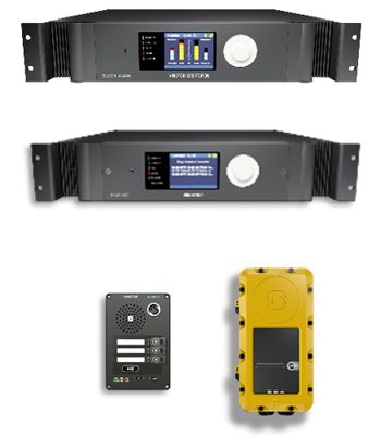
This article describes the control outputs in the Exigo system in general.
- Control Outputs are available on:
- System Controller
- Amplifiers
- Access Panels (Not Ex panels)
- Rack Devices (Controllers/Amplifiers):
- 6 NO/NC relays and 24V DC outputs (200 mA)
- Access Panels:
- 2 NO/NC relays, and 6 digital outputs
- Outputs are used, e.g. for:
- Visual Call / Audio Indication
- Local Mute of nearby loudspeakers
- Volume Override
Contents
Control Outputs - Connections
Connections on Rack Devices:
Connections on Access Panels:
Configuration
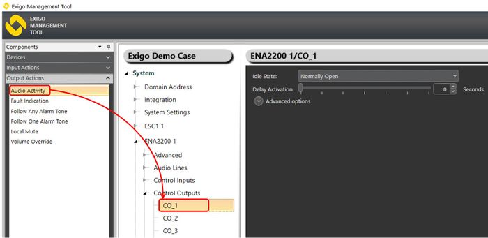
Configuration of Control Outputs are done in EMT:
- In Components view open Output Actions
- In System, identify the device and expand to Control Outputs
- Drag the desired Output Action to Control Output > CO_x
- Set relevant parameters in the dialog box that appears
Advanced Options:
- Limit High Not OK: When the Control Output is cleared, and feedback voltage is at or above this value, the output is considered fed with alien voltage.
- Limit Low OK: When the Control Output is set, and feedback voltage is above this value, the output is considered active OK.
- On Lost Connection: Fall back to this state on lost connection with ESC. Available Settings: Idle State, No Change, Open, Closed.
Limitations
ENA Amplifiers
Relay Outputs:
- Max 24 VDC, 60 W
- Max 250 VAC, 125 VA
24 VDC Outputs:
- 24 VDC, ±10%, 200 mA
Access Panels
Relay Outputs: 2 (250VAC/200VDC, 2A, 60W)


