Difference between revisions of "Control Inputs"
(Tag: Visual edit) |
|||
| Line 1: | Line 1: | ||
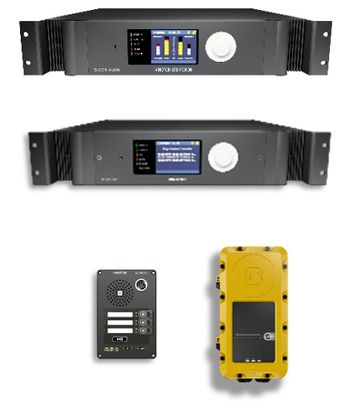
[[File:Control Inputs 1.JPG|thumb|right|350px|Devices with Control Inputs available]] | [[File:Control Inputs 1.JPG|thumb|right|350px|Devices with Control Inputs available]] | ||
| − | This article describes the | + | This article describes the Control Inputs on the Exigo system in general. <br> |
*'''Control Inputs''' are available on: | *'''Control Inputs''' are available on: | ||
** [[ESC1|System Controller]] | ** [[ESC1|System Controller]] | ||
** Amplifiers | ** Amplifiers | ||
| − | ** [[:Category:Access Panels|Access Panels]] and | + | ** [[:Category:Access Panels|Access Panels]] and Kits ('''Not''' Ex panels) |
* 6 inputs on each device | * 6 inputs on each device | ||
| − | * Inputs are used e.g. for triggering: | + | * Inputs are used, e.g. for triggering: |
** General Alarm | ** General Alarm | ||
** Fire Alarm | ** Fire Alarm | ||
| Line 14: | Line 14: | ||
== Control Inputs - Connections == | == Control Inputs - Connections == | ||
| − | '''Connections on | + | '''Connections on Rack Devices''' |
[[File:Control Inputs 2.JPG|thumb|left|700px|Rack devices]] | [[File:Control Inputs 2.JPG|thumb|left|700px|Rack devices]] | ||
<br style="clear:both;" /> | <br style="clear:both;" /> | ||
| − | '''Connections on | + | '''Connections on Access Panels''' |
[[File:Control Inputs 3.JPG|thumb|left|700px|Kits and access panels]] | [[File:Control Inputs 3.JPG|thumb|left|700px|Kits and access panels]] | ||
<br style="clear:both;" /> | <br style="clear:both;" /> | ||
== Configuration == | == Configuration == | ||
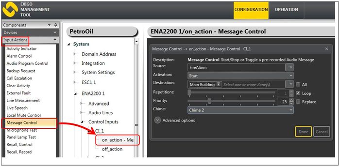
| − | Configuration of Control Inputs | + | Configuration of Control Inputs is done in EMT: |
[[File:Control Inputs 4.JPG|thumb|left|700px|Input 1 on amplifier starts «Fire Alarm» message in «Main Building»]] | [[File:Control Inputs 4.JPG|thumb|left|700px|Input 1 on amplifier starts «Fire Alarm» message in «Main Building»]] | ||
<br style="clear:both;" /> | <br style="clear:both;" /> | ||
* In '''Components''' view open '''Input Actions''' | * In '''Components''' view open '''Input Actions''' | ||
| − | * In '''System, identify the device and expand to '''Control Inputs | + | * In '''System, identify the device and expand to '''Control Inputs |
* Drag the desired '''Input Action''' to the '''on_action''' or the '''off_action''' | * Drag the desired '''Input Action''' to the '''on_action''' or the '''off_action''' | ||
* Set relevant parameters in the dialog box that appears | * Set relevant parameters in the dialog box that appears | ||
| Line 77: | Line 77: | ||
=== Monitored === | === Monitored === | ||
| − | 11,1V <–> 8,2 V = Not connected <br/> | + | 11,1V <–> 8,2 V = Not connected <br /> |
| − | 8,2V <-> 6,2 V = Open <br/> | + | 8,2V <-> 6,2 V = Open <br /> |
| − | 6,2V <-> 2 V = Closed<br/> | + | 6,2V <-> 2 V = Closed<br /> |
2V <-> 0 = Shorted | 2V <-> 0 = Shorted | ||
| − | |||
[[Category:Integration]] | [[Category:Integration]] | ||
[[Category:Input Actions]] | [[Category:Input Actions]] | ||
Revision as of 15:30, 15 December 2016
This article describes the Control Inputs on the Exigo system in general.
- Control Inputs are available on:
- System Controller
- Amplifiers
- Access Panels and Kits (Not Ex panels)
- 6 inputs on each device
- Inputs are used, e.g. for triggering:
- General Alarm
- Fire Alarm
- Live Speech from external microphone
Contents
Control Inputs - Connections
Connections on Rack Devices
Connections on Access Panels
Configuration
Configuration of Control Inputs is done in EMT:
- In Components view open Input Actions
- In System, identify the device and expand to Control Inputs
- Drag the desired Input Action to the on_action or the off_action
- Set relevant parameters in the dialog box that appears
Control Inputs - Monitoring
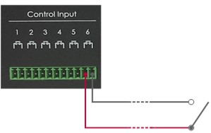
- Conventional inputs have two states:
- Contact is Open, or
- Contact is Closed
This makes the control input vulnerable - cable break is not detected.
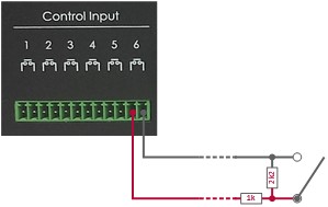
On System Controller and Amplifiers it is possible to monitor the control inputs. Access panels do not support monitoring.
This is done by connecting two resistors as close as possible to the external switch/relay, one in series and one in parallell.
The resistor connected in series with the external switch/relay shall have a value of 1 kΩ, while the resistor connected in parallel shall be 2.2 kΩ.
Monitored Inputs have four states:
- Contact is Open, or
- Contact is Closed
- Short circuit (error)
- Open circuit (error)
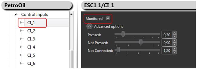
Monitoring of inputs must be enabled in EMT:
Parallel Wired Inputs
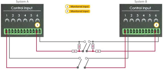
In an A-B system, it is required that signals from external systems such as fire detection are routed to both the A and B systems.
Connection with Dual-Pole Switch
If the external system has two physical outputs, a dual-pole switch connection must be made between Exigo and the external system as shown below:
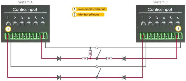
Connection with Single-Pole Switch
If the external system has only one physical output, a single-pole switch connection must be made between Exigo and the external system as shown below:
As the Exigo system uses a small current to detect the status of the external switch/relay, two inputs should not be directly connected together without due precautions.
To prevent currents from flowing the wrong way, and to ensure proper functioning of the control input, blocking diodes must be inserted in the loop as depicted in the figure above.
Voltage Levels
Control input is designed around a voltage measurement. Normal voltage will be 11,7V when nothing is connected.
Non monitored
Voltage measured on pins under 6,2 Volt is considered to be closed. Above 6,2 Volt and is considered to be open.
Monitored
11,1V <–> 8,2 V = Not connected
8,2V <-> 6,2 V = Open
6,2V <-> 2 V = Closed
2V <-> 0 = Shorted
