Backup Amplifier Wiring
This article describes how to wire the backup amplifier solution. Exigo ENA Amplifiers have inbuilt support for backup amplifier switch-over where one amplifier can be designated as backup for up to six other amplifiers.
Contents
Hardware requirements
The backup functionality is supported by the following amplifiers:
Wiring
The backup amplifier needs to be wired to the amplifier(s) it should monitor:
- One control output (24V DC) from the backup amplifier is connected to each of the backed-up amplifiers (star wiring).
- The speaker loop outputs from the backup amplifier are connected to the backup inputs on all amplifiers being backed up (bus wiring).
In addition, an optional function on a control input on the backup amplifier can trigger the backup functionality. This will ensure an even faster switch-over if the defective amplifier has a power issue.
- Wire the Control Output on the backed-up amplifier to the Control Input on the backup amplifier.
Standard Backup Wiring Example
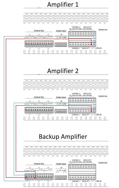
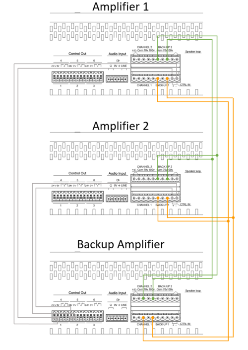
In the figures below, we have a backup amplifier that is on hot standby for two amplifiers.
Control Output/Input Wiring:
The red and blue wiring is the control outputs from the backup amplifier to the two backed-up amplifiers:
- Control Output 1 (24V DC) on the Backup Amplifier is wired to the control in (labeled CTRL IN) on Amplifier 1.
- Control Output 2 (24V DC) on the Backup Amplifier is wired to the control in (labeled CTRL IN) on Amplifier 2.
Speaker Output/Input Wiring:
The orange and green wires are the 100V speaker lines:
- Channel 1 output on the Backup Amplifier is wired to channel 1 backup input (labeled BACK-UP 1) on Amplifier 1 and Amplifier 2.
- Channel 2 output on the Backup Amplifier is wired to Channel 2 backup input (labeled BACK-UP 2) on Amplifier 1 and Amplifier 2.
Optional Switch-Over Wiring Example
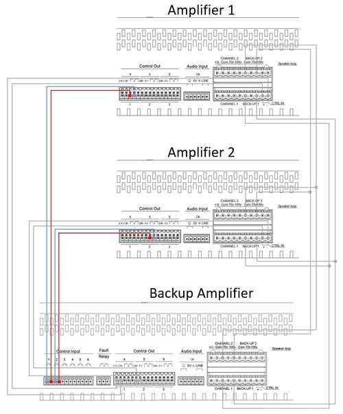
The figure below illustrates how the optional switch-over wiring is done.
The red and blue wiring are the control outputs from the backed-up amplifiers to the backup amplifiers:
- Control Output 1 (NO - Normally Open) on Amplifier 1 is wired to Control Input 1 on the Backup Amplifier.
- Control Output 2 (NO - Normally Open) on Amplifier 2 is wired to Control Input 2 on the Backup Amplifier.
Please be aware that the standard backup wiring must also be done to make the optional switch-over work.
Availability
This function is available from Exigo 1.3 and newer.


