Difference between revisions of "Modbus Interface"
(→Trig announcement in Exigo from Modbus) |
(→Trig announcement in Exigo from Modbus) |
||
| Line 30: | Line 30: | ||
A subset of physical Control Input actions is available for programming the Modbus Coil Events using [[:Category:EMT| Exigo Management Tool (EMT)]]: | A subset of physical Control Input actions is available for programming the Modbus Coil Events using [[:Category:EMT| Exigo Management Tool (EMT)]]: | ||
| − | * [[Message Control]] | + | * [[Message Control]] |
* Feed audio from an audio input to a set of zones | * Feed audio from an audio input to a set of zones | ||
* Play a predefined alarm signal to a set of zones | * Play a predefined alarm signal to a set of zones | ||
Revision as of 10:49, 19 March 2019
This article describes the Modbus interface available in Exigo.
The Modbus Interface is not official implemented.
The Exigo Controller implements a Modbus TCP slave (server) interface on the standard Modbus port, TCP port 502. The Modbus interface in Exigo has two main features:
- Status about amplifiers and panels connected to the Controller can be read from Modbus 16 bit input registers
- Pre-programmed PA calls and announcements can be triggered by writing to Modbus coil registers.
Contents
Exigo status to Modbus
Selected Exigo failure statuses are exported to Modbus 16 bit input registers. The allocation of registers and bits is fixed.
There is no configuration of this feature (except for opening up Modbus in firewall). SCADA must poll these registers. A range of input registers can be read using Modbus function code 2.
There is one 16 bit register for each panel, amplifier and amplifier line. Physical devices like panels and amplifier have one 16 bit register describing the device level status.
Amplifiers have in addition one 16 bit register for each audio line. The index of each device and line is displayed in the Exigo Management Tool (EMT) in the "StInd" field.
The 16 bit device/line statuses is interpreted as a bitmap:
- Bit 0 is set in all registers that represent a configured item. Unused registers read as zero.
- Remaining bits may be set to indicate a fault situation.
- Bit 1 on device level statuses means the controller has lost contact with the device.
- Bit 2 on speaker line mean that the speaker line is faulty (voltage test).
Trig announcement in Exigo from Modbus
Modbus coil registers 1 - 100 in the controller can be assigned a pre-programmed action in Exigo.
SCADA set a "coil" bit (function code 5) to trig the action. Actions can be pre-programmed on both set (1) and clear (0), or just on one of the transitions.
Seen from SCADA these are discrete outputs. In Exigo those are seen as Modbus Coil Events.
At startup, the Modbus coil registers have value zero.
A subset of physical Control Input actions is available for programming the Modbus Coil Events using Exigo Management Tool (EMT):
- Message Control
- Feed audio from an audio input to a set of zones
- Play a predefined alarm signal to a set of zones
- Clear a specific call
- Clear all calls in given zones
Unlike a physical Control Input, the matching Modbus action is triggered also when the same coil register value is written multiple times.
Configuration
Firewall
To make the Exigo Controller able to receive Modbus connections, TCP port 502 have to be opened in "AlphaWeb" of the controller: https://wiki.zenitel.com/wiki/AlphaWeb#Filters.
First add TCP port 502 as new protocol, then open it for the desired interface(s).
EMT Configuration
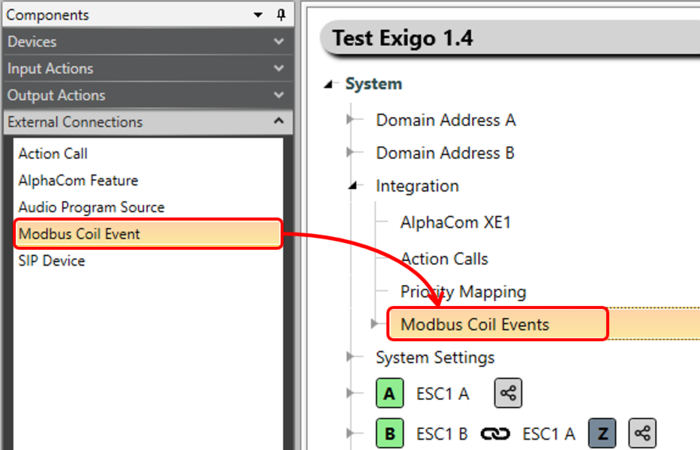
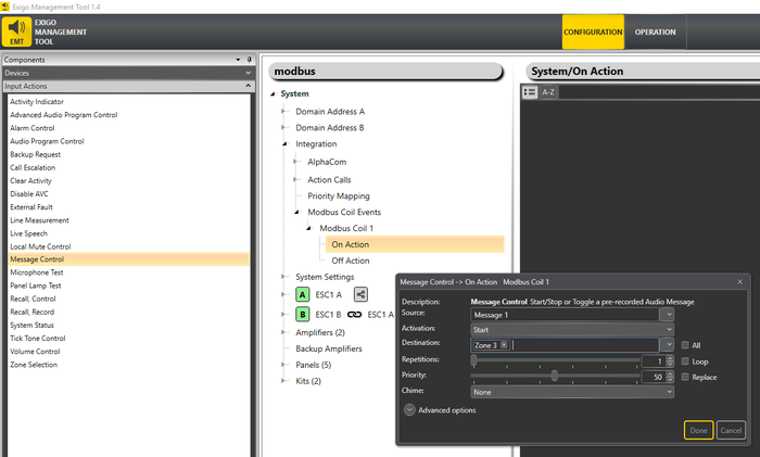
To create configuration for Modbus Coil Event: Drag and drop Modbus Coil Event -> System -> Integration -> Modbus Coil Events:
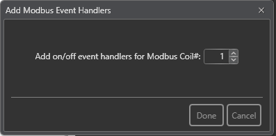
A dialog box will appear where the Coil number can be set:
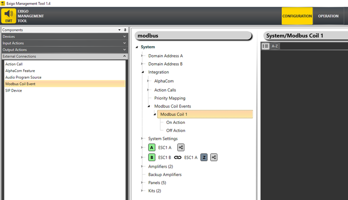
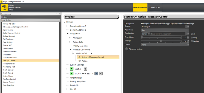
Click "Done". Placeholders for event configuration will be added to the Configuration Tree:
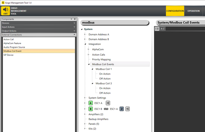
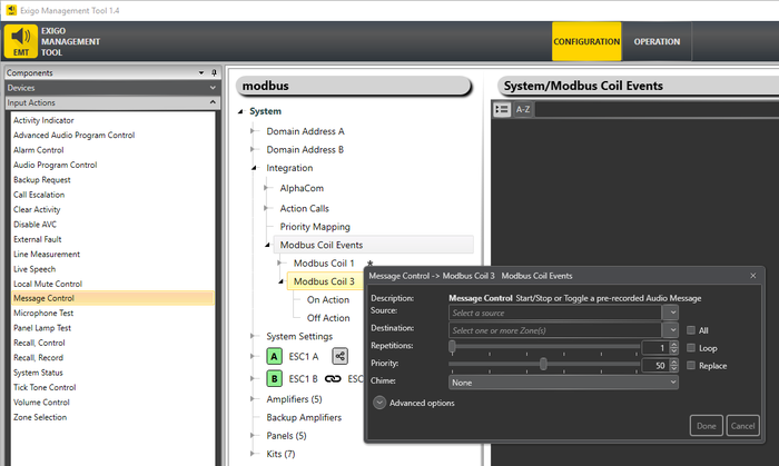
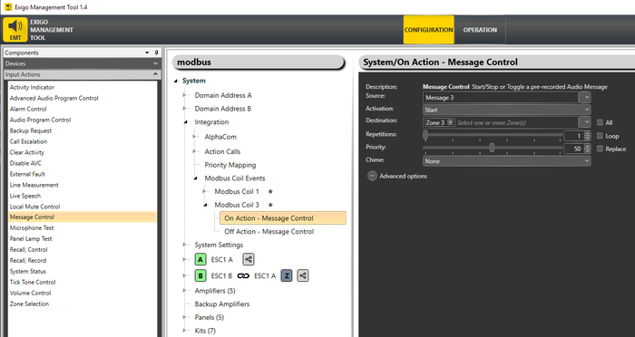
It is possible to create multiple Modbus Coil Events:
Input Actions is configured the same way Control Input and Direct Access Keys:
It is also possible to drop the Input Action on the Modbus Coil event to automatically create Start/Stop Actions on "On Action" and "Off Action":
Input Actions currently available for configuration on Modbus Coil Events are:
- Alarm Control
- Message Control
- Audio Program Control
- Recall, Control
- Recall, Record
- Tick Tone Control
- Local Mute Control
- Line Measurement
- Clear Activity
- Volume Control
Test tool
For standalone testing of Modbus interface, the command line tool "mbpoll" is useful: https://github.com/epsilonrt/mbpoll
| Set coil#2 to 1 | mbpoll 1.2.3.4 -1 -t 0 -r 2 1 |
| Set coil#2 to 0 | mbpoll 1.2.3.4 -1 -t 0 -r 2 0 |
| Read 30 first input registers | mbpoll 1.2.3.4 -1 -t 3 -c 30 |
Availability
The Modbus functionality is not yet official implemented.
Please contact AlphaSupport if you are interested in the Modbus functionality.
