Difference between revisions of "Backup Amplifier Wiring"
| (21 intermediate revisions by 2 users not shown) | |||
| Line 1: | Line 1: | ||
This article describes how to wire the backup amplifier solution. | This article describes how to wire the backup amplifier solution. | ||
Exigo ENA Amplifiers have inbuilt support for backup amplifier switch-over where one amplifier can be designated as backup for up to six other amplifiers. | Exigo ENA Amplifiers have inbuilt support for backup amplifier switch-over where one amplifier can be designated as backup for up to six other amplifiers. | ||
| + | |||
| + | == Hardware requirements == | ||
| + | The backup functionality is supported by the following amplifiers: | ||
| + | * [[ENA2200]] | ||
| + | * [[ENA2400-DC]] | ||
| + | * [[ENA2400-AC]] | ||
==Wiring== | ==Wiring== | ||
The backup amplifier needs to be wired to the amplifier(s) it should monitor: | The backup amplifier needs to be wired to the amplifier(s) it should monitor: | ||
| − | * One control output (24V DC) from the backup amplifier is connected to each of the backed up amplifiers (star wiring). | + | * One control output (24V DC) from the backup amplifier is connected to each of the backed-up amplifiers (star wiring). |
| − | * The speaker loop outputs from the backup amplifier | + | * The speaker loop outputs from the backup amplifier are connected to the backup inputs on all amplifiers being backed up (bus wiring). |
| + | |||
| + | In addition, an optional function on a control input on the backup amplifier can trigger the backup functionality. | ||
| + | This will ensure an even faster switch-over if the defective amplifier has a power issue. | ||
| + | * Wire the Control Output on the backed-up amplifier to the Control Input on the backup amplifier. | ||
| + | |||
| + | ==Standard Backup Wiring Example== | ||
| + | In the figures below, we have a backup amplifier that is on hot standby for two amplifiers. | ||
| + | |||
| + | '''<u>Control Output/Input Wiring:</u>'''<br> | ||
| + | |||
| + | [[File:Backup_amplifier_wiring_1.JPG|thumb|left|500px|Control output to control input wiring]] | ||
| + | <br style="clear:both;" /> | ||
| + | |||
| + | The red and blue wiring is the control outputs from the backup amplifier to the two backed-up amplifiers: | ||
| + | * '''Control Output 1''' ('''24V DC''') on the Backup Amplifier is wired to the control in (labeled '''CTRL IN''') on Amplifier 1. | ||
| + | * '''Control Output 2''' ('''24V DC''') on the Backup Amplifier is wired to the control in (labeled '''CTRL IN''') on Amplifier 2. | ||
| + | |||
| + | '''<u>Speaker Output/Input Wiring:</u>'''<br> | ||
| + | |||
| + | [[File:Backup amplifier wiring 2.png|thumb|left|500px|Speaker lines wiring]] | ||
| + | <br style="clear:both;" /> | ||
| + | |||
| + | The orange and green wires are the 100V speaker lines: | ||
| + | * '''Channel 1''' output on the Backup Amplifier is wired to channel 1 backup input (labeled '''BACK-UP 1''') on Amplifier 1 '''and''' Amplifier 2. | ||
| + | * '''Channel 2''' output on the Backup Amplifier is wired to Channel 2 backup input (labeled '''BACK-UP 2''') on Amplifier 1 '''and''' Amplifier 2. | ||
| + | |||
| + | ==Optional Switch-Over Wiring Example== | ||
| + | The figure below illustrates how the optional switch-over wiring is done. | ||
| + | |||
| + | [[File:Backup_amplifier_wiring_3.JPG|thumb|left|500px|Optional switch-over wiring]] | ||
| + | <br style="clear:both;" /> | ||
| + | |||
| + | The red and blue wiring are the control outputs from the backed-up amplifiers to the backup amplifiers: | ||
| + | |||
| + | * Control Output 1 ('''NO - Normally Open''') on Amplifier 1 is wired to '''Control Input 1''' on the Backup Amplifier. | ||
| + | * Control Output 2 ('''NO - Normally Open''') on Amplifier 2 is wired to '''Control Input 2''' on the Backup Amplifier. | ||
| + | Please be aware that the standard backup wiring must also be done to make the optional switch-over work. | ||
| + | == Availability == | ||
| + | This function is available from Exigo 1.3 and newer. | ||
| − | [[ | + | [[Category:Exigo features]] |
Latest revision as of 07:48, 29 August 2019
This article describes how to wire the backup amplifier solution. Exigo ENA Amplifiers have inbuilt support for backup amplifier switch-over where one amplifier can be designated as backup for up to six other amplifiers.
Contents
Hardware requirements
The backup functionality is supported by the following amplifiers:
Wiring
The backup amplifier needs to be wired to the amplifier(s) it should monitor:
- One control output (24V DC) from the backup amplifier is connected to each of the backed-up amplifiers (star wiring).
- The speaker loop outputs from the backup amplifier are connected to the backup inputs on all amplifiers being backed up (bus wiring).
In addition, an optional function on a control input on the backup amplifier can trigger the backup functionality. This will ensure an even faster switch-over if the defective amplifier has a power issue.
- Wire the Control Output on the backed-up amplifier to the Control Input on the backup amplifier.
Standard Backup Wiring Example
In the figures below, we have a backup amplifier that is on hot standby for two amplifiers.
Control Output/Input Wiring:
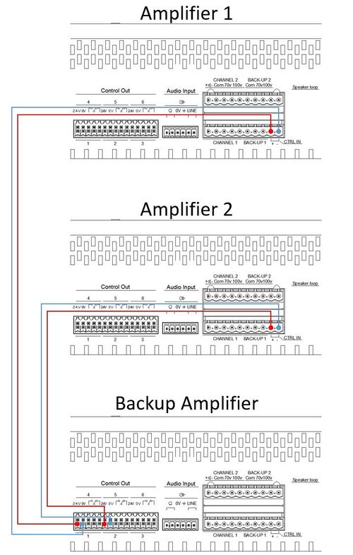
The red and blue wiring is the control outputs from the backup amplifier to the two backed-up amplifiers:
- Control Output 1 (24V DC) on the Backup Amplifier is wired to the control in (labeled CTRL IN) on Amplifier 1.
- Control Output 2 (24V DC) on the Backup Amplifier is wired to the control in (labeled CTRL IN) on Amplifier 2.
Speaker Output/Input Wiring:
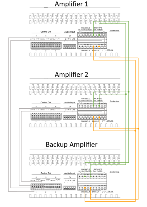
The orange and green wires are the 100V speaker lines:
- Channel 1 output on the Backup Amplifier is wired to channel 1 backup input (labeled BACK-UP 1) on Amplifier 1 and Amplifier 2.
- Channel 2 output on the Backup Amplifier is wired to Channel 2 backup input (labeled BACK-UP 2) on Amplifier 1 and Amplifier 2.
Optional Switch-Over Wiring Example
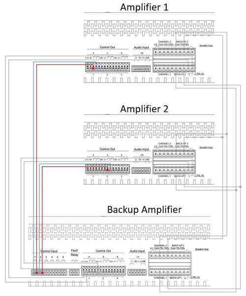
The figure below illustrates how the optional switch-over wiring is done.
The red and blue wiring are the control outputs from the backed-up amplifiers to the backup amplifiers:
- Control Output 1 (NO - Normally Open) on Amplifier 1 is wired to Control Input 1 on the Backup Amplifier.
- Control Output 2 (NO - Normally Open) on Amplifier 2 is wired to Control Input 2 on the Backup Amplifier.
Please be aware that the standard backup wiring must also be done to make the optional switch-over work.
Availability
This function is available from Exigo 1.3 and newer.


