Difference between revisions of "Fault Indication"
(→Parameter Details) |
(→Parameter Details) |
||
| (4 intermediate revisions by the same user not shown) | |||
| Line 30: | Line 30: | ||
==Parameter Details== | ==Parameter Details== | ||
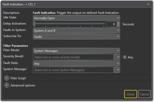
| + | [[File:Fault indication 4.png|thumb|left|500px|Fault Indication configuration]] | ||
| + | <br style="clear:both;" /> | ||
| + | |||
'''<u>Idle State</u>''' <br> | '''<u>Idle State</u>''' <br> | ||
Sets the idle state for the output. The options are '''Normally Open''' or '''Normally Closed'''. | Sets the idle state for the output. The options are '''Normally Open''' or '''Normally Closed'''. | ||
| Line 44: | Line 47: | ||
=== <u>Filter Parameters:</u> === | === <u>Filter Parameters:</u> === | ||
'''<u>Filter Mode:</u>''' | '''<u>Filter Mode:</u>''' | ||
| + | :: '''System Messages''' | ||
| + | :: Trigger on System Message(s) in the system. | ||
:: '''Zones / Affected Zones''' | :: '''Zones / Affected Zones''' | ||
:: Trigger on faults that affect selected zones. | :: Trigger on faults that affect selected zones. | ||
| Line 55: | Line 60: | ||
Trigger on faults in selected state. Options are: '''Any''', '''Active'''. <br> | Trigger on faults in selected state. Options are: '''Any''', '''Active'''. <br> | ||
'''<u>System Message:</u>''' <br> | '''<u>System Message:</u>''' <br> | ||
| − | Trigger on faults that have selected messages. | + | Trigger on faults that have selected messages. <br> |
List of system messages available can be found [[Fault Indication System Message|here]]. | List of system messages available can be found [[Fault Indication System Message|here]]. | ||
Latest revision as of 11:27, 18 October 2018
The Fault Indication function is used to trigger the control output on faults or warnings in the system.
This can be used to send a signal to external systems such as BMS (Building Management Systems)). It can also be used to provide visual notifications when there is fault in the system.
Contents
Assigning Fault Indication to a Control Output
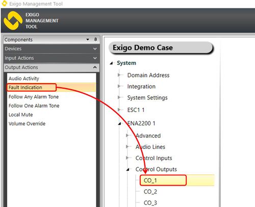
To assign the function Fault Indication to an Control Output:
- In Components view, open Output Actions
- In System, identify the Controller, the Amplifier or the Access Panel to be used, and expand to Device > Control Outputs.
- Drag Fault Indication to the Control Output you want to use.
Configuration
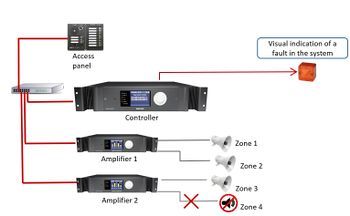
Visual Indication of a Fault in the System
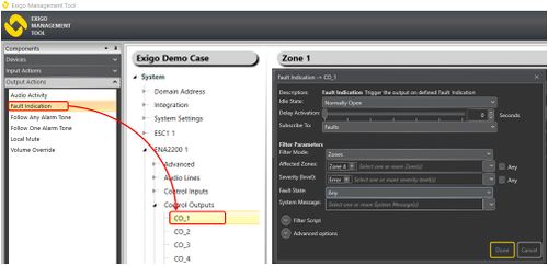
In this example, the output is used to give a visual indication of an error in Zone 4.
- Under Output Actions, drag Fault Indication to the desired Control Output
- Select Zones in Filter Mode. This will give you the option to select zones
- Select Zone 4 in Affected Zones
- In Severity (level) select Error
In this example, an error in Zone 4 will trigger Control Output 1.
Parameter Details
Idle State
Sets the idle state for the output. The options are Normally Open or Normally Closed.
Delay Activation
Delays control output activation for the stipulated number of seconds when triggered.
Faults in System (only available in A-B System projects)
The system, i.e. System A, System B, or System A and B, from which faults will be received .
Subscribe To
Options are Faults or Warnings.
Filter Parameters:
Filter Mode:
- System Messages
- Trigger on System Message(s) in the system.
- Zones / Affected Zones
- Trigger on faults that affect selected zones.
- Devices / Affected Devices
- Trigger on faults that affect selected devices.
- Devices / Affected Lines
- Trigger on faults that affect selected audio lines.
Severity (level):
Trigger on faults at selected levels. Options are: Emergency, Alert, Critical, Error.
Fault State:
Trigger on faults in selected state. Options are: Any, Active.
System Message:
Trigger on faults that have selected messages.
List of system messages available can be found here.
Filter Script
- Filter Script field will show the actual script which will be used to determine if output should be triggered or not. This script is constructed based on the selection of filter parameters.
Advanced Options:
- Limit High Not OK: When the Control Output is cleared, and feedback voltage is at or above this value, the output is considered fed with alien voltage.
- Limit Low OK: When the Control Output is set, and feedback voltage is above this value, the output is considered active OK.
- On Lost Connection: Fall back to this state on lost connection with ESC. Available Settings: Idle State, No Change, Open, Closed.
To avoid errors one fault indication should not mix Zones and Channels.
Example of Use:
Case 1: System Messages
The system should trigger a control output connected to another system if any device is missing. Fault indication will in this example be configured as:
- Filter Mode: System Messages
- System Message: Missing device
Case 2: Zones
The system should trigger a control output connected to another system if there is a fault which affects Zone 2.
Fault indication will in this example be configured as:
- Filter Mode: Zones
- Affected Zones: Zone 2
Case 3: Custom Fault
The system should trigger a control output connected to another system if one of the external faults are triggered . Fault indication will in this example be configured as:
- Filter Mode: System Messages
- System Message: External fault
This will trigger on any external fault in the system. If more granularity is required then Filter Mode = Devices can be used to only trigger on external faults from a specific device.


