Difference between revisions of "Control Inputs"
Jump to navigation
Jump to search
| Line 30: | Line 30: | ||
* Drag the desired '''Input Action''' to the '''on_action''' or the '''off_action''' | * Drag the desired '''Input Action''' to the '''on_action''' or the '''off_action''' | ||
* Set relevant parameters in the dialog box that appears | * Set relevant parameters in the dialog box that appears | ||
| + | |||
| + | ==Control Inputs - Monitoring== | ||
| + | * Conventional inputs have two states: | ||
| + | ** Contact is Open, or | ||
| + | ** Contact is Closed | ||
| + | This makes the control input vulnerable - cable break is not detected. | ||
| + | |||
| + | On System Controller and Amplifiers it is possible to monitor the control inputs. | ||
| + | This is done by connecting two resistors as close as possible to the external switch/relay, one in series and one in parallell. | ||
| + | |||
| + | The resistor connected in series with the external switch/relay shall have a value of '''1 kΩ''', while the resistor connected in parallel shall be '''2.2 kΩ'''. | ||
| + | |||
| + | |||
| + | Monitored Inputs have four states: | ||
| + | * Contact is Open, or | ||
| + | * Contact is Closed | ||
| + | * Short circuit (error) | ||
| + | * Open circuit (error) | ||
| + | |||
Revision as of 12:24, 7 July 2016
This article describes the control inputs on Exigo in general.
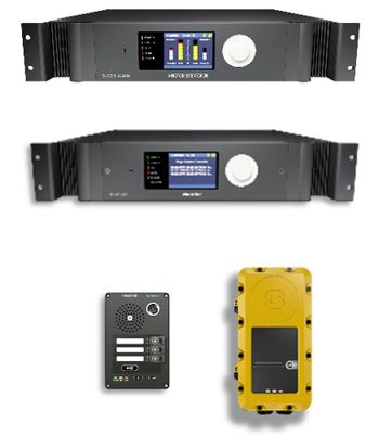
- Control Inputs are available on:
- System Controller
- Amplifiers
- Access Panels (Not EX panels)
- 6 inputs on each device
- Inputs are used e.g. for triggering:
- General Alarm
- Fire Alarm
- Live Speech from external microphone
Control Inputs - Connections
Connections on rack devises
Connections on access panels
Configuration
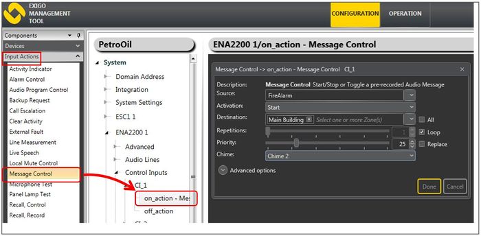
- In Components view open Input Actions
- In System, identify the device and expand to Control Inputs
- Drag the desired Input Action to the on_action or the off_action
- Set relevant parameters in the dialog box that appears
Control Inputs - Monitoring
- Conventional inputs have two states:
- Contact is Open, or
- Contact is Closed
This makes the control input vulnerable - cable break is not detected.
On System Controller and Amplifiers it is possible to monitor the control inputs. This is done by connecting two resistors as close as possible to the external switch/relay, one in series and one in parallell.
The resistor connected in series with the external switch/relay shall have a value of 1 kΩ, while the resistor connected in parallel shall be 2.2 kΩ.
Monitored Inputs have four states:
- Contact is Open, or
- Contact is Closed
- Short circuit (error)
- Open circuit (error)


