TKIE-1
Voip Intercom Module
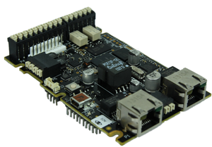
The TKIE-1 is the extended version of our Turbine Kit range. It offers the same high quality audio as the TKIS-x kit, but adds to the feature list with an extra RJ45 port for dual Ethernet connectivity, dual relays, and a header for easy connection of audio accessories. For high-power applications, the TKIE-1 may be complemented with the TA-10 Relay Module which offers 2 DPDT relays suited for high-voltage/high-current applications.
- IP station kit with extended functionality
- Dual RJ45 for Ethernet connectivity (with switch)
- Dual relays (DPDT)
- 6 configurable I/Os (input, output or LED-driving)
- Line-in/Line-out connectivity for connection to audio devices
- Header for connecting audio accessories
- Possibility for connecting high-power relay module (TA-10)
- High quality Turbine™ class output with 10W amplifier
- Full open duplex and digital noise reduction
Contents
Additional documentation
For more documentation, please visit the Zenitel web page: https://www.zenitel.com/product/tkie-1
Connections
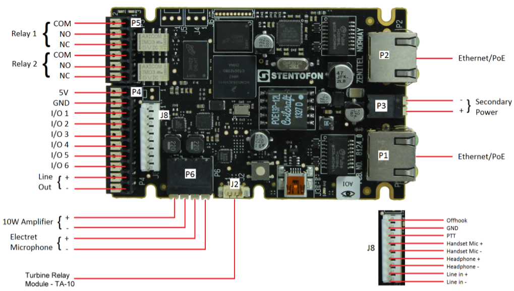
There are two RJ-45 ports located on the TKIE-1 that are used for PoE/LAN Ethernet connection.
There are 6 I/O connection options for the TKIE-1. These connections are used as digital input (eg. form a closing contact), digital output (5V), or LED driving (20mA max) for connecting sensors, indicators or integration to other systems.
| Ethernet/Power | The TKIE-1 supports Power over Ethernet (PoE, IEEE 802.3 a-f) where power can be drawn from either the spare line or signal line.* |
| Secondary Power | If PoE in not available, the TKIE-1 can be powered from a 24-48 VDC local power supply.** |
| Relays | There are two Double Throw relay contacts with 60W switching power. COM, NO, NC contacts are provided. |
| Input/Output | 6 I/Os are available. Each I/O can be configured as either input, output, or LED driver. |
| Audio Line Out | A balanced 600 ohm audio line out with induction loop signal |
Note! Use cables crimped with ferrules for terminal block connectors
*If connected to two PoE-capable switches, only one of the ports will negotiate PoE; hence this is not a good solution for
power redundancy (switch failure might lead to a reboot). Instead a “dumb” PoE injector (spare-pair power) should be used
for the two Ethernet ports or a local 24 VDC local power backup.
**If used together with PoE the station can be powered by 24 VDC as a local power backup.
- When the TKIE-1 is connected to the network, its IP address is automatically obtained from a DHCP server or an IP address in the range 169.254.x.x will be assigned.
P1&P2 RJ45 PoE port for 10/100 Mbit Ethernet connection.
- The station can be powered from this port if the line supports Power over Ethernet (PoE).
P3 Secondary Power; 24-48VDC
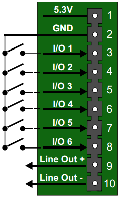
P4 10-pin plug-on terminal for external connections.
- Pin 1 5.3V
- Pin 2 GND
- Pin 3 Button Input or LED Driver
- Pin 4 Button Input or LED Driver
- Pin 5 Button Input or LED Driver
- Pin 6 Button Input or LED Driver
- Pin 7 Button Input or LED Driver
- Pin 8 Button Input or LED Driver
- Pin 9 600 ohm balanced line out +
- Pin 10 600 ohm balanced line out -1
P5 6-pin plug-on terminal for external connections.
- Pin 1 COM relay 1
- Pin 2 NO relay 1
- Pin 3 NC relay 1
- Pin 4 COM relay 2
- Pin 5 NO relay 2
- Pin 6 NC relay 2
Note! Relay 1 is configured as output 7, and Relay 2 is configured as output 8!
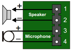
P6 Loudspeaker & Electret microphone
- Pin 1 10W Speaker amplifier +
- Pin 2 10W Speaker amplifier -
- Pin 3 Electret Microphone +
- Pin 4 Electret Microphone -
J2 Turbine Relay Module - TA-10
Note! Relay 3 is configured as output 9, and Relay 4 is configured as output 10!
J8 Headset/Handset connector
- Pin 1 Offhook
- Pin 2 GND
- Pin 3 PTT
- Pin 4 Handset Mic Positive
- Pin 5 Handset Mic Negative
- Pin 6 Headphone Positive
- Pin 7 Headphone Negative
- Pin 8 Line In Positive
- Pin 9 Line In Negative
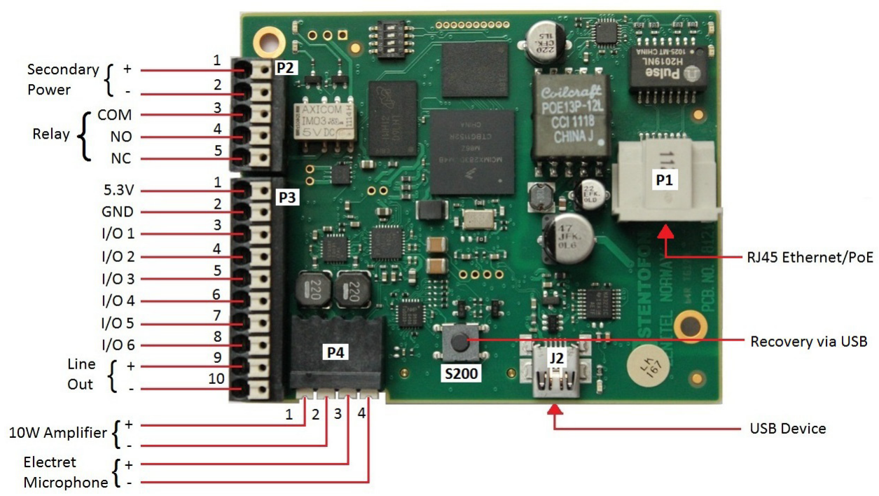
The TKIS-2 has an RJ-45 PoE/LAN port, and 6-pin & 10-pin external connectors.
| Ethernet/Power | 10/100 Mbps Ethernet RJ-45 port for LAN (uplink) connection. Supports PoE (802.3af). Draws power from either spare line or signal line. |
| Secondary Power | 24 VDC (16 – 48 V) secondary power is provided from an external adapter. |
| Relays | There is one Double Throw relay contact with 60W switching power. COM, NO, NC contacts are provided. |
| Input/Output | 6 I/Os are available. Each I/O can be configured as either input, output, or LED driver. |
| Audio Line Out | A balanced 600 ohm audio line out with induction loop signal |
Note! Use cables crimped with ferrules for terminal block connectors
- When the TKIS-2 is connected to the network, its IP address is automatically obtained from a DHCP server or an IP address in the range 169.254.x.x will be assigned.
PCB - Front
P1 RJ45 PoE port for 10/100 Mbit Ethernet connection.
- The station can be powered from this port if the line supports Power over Ethernet (PoE).
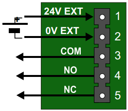
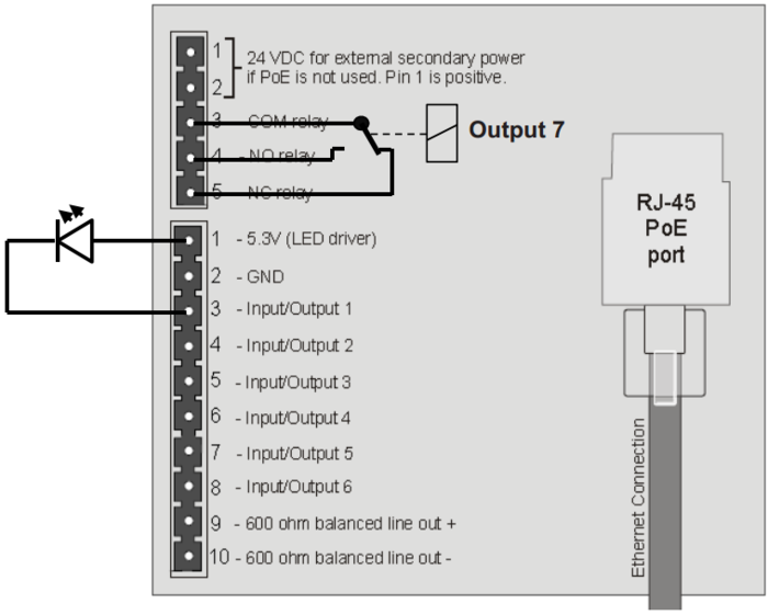
P2 6-pin plug-on terminal for external connections.
- Pin 1/2 24 VDC for external secondary power if PoE is not used. Pin 1 is positive.
- Pin 3 COM relay
- Pin 4 NO relay
- Pin 5 NC relay
The relay can switch and carry continously 60W power maximum.
So with maximum current 2A, it can take maximum 30V, or with maximum voltage 250VAC it can take maximum 240mA.
P4 Loudspeaker & Electret microphone
- Pin 1 10W Speaker amplifier +
- Pin 2 10W Speaker amplifier -
- Pin 3 Electret Microphone +
- Pin 4 Electret Microphone -
Input Connectors
P3 10-pin plug-on terminal for external connections.
- Pin 1 5.3V (max. 200mA current)
- Pin 2 GND
- Pin 3 Button Input or LED Driver
- Pin 4 Button Input or LED Driver
- Pin 5 Button Input or LED Driver
- Pin 6 Button Input or LED Driver
- Pin 7 Button Input or LED Driver
- Pin 8 Button Input or LED Driver
- Pin 9 600 ohm balanced line out +
- Pin 10 600 ohm balanced line out -
Output Connectors + 1 relay
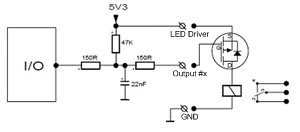
The extra relay for any of the 6 I/O pins is connected as shown:
Most general purpose P-Channel MOSFET's should work. Recommended example: BSS84
The 5,3V output can deliver 200mA current maximum
PCB - Rear
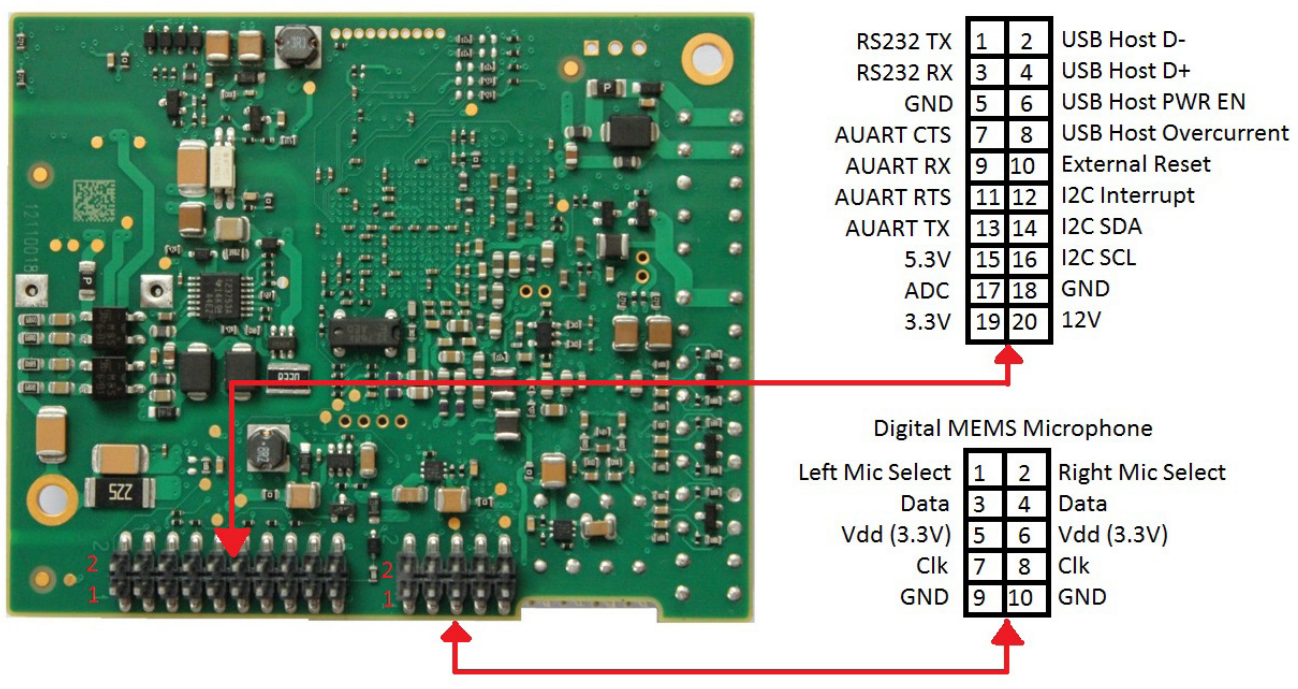
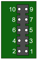
J6 10-pin terminal for digital MEMS Microphone
- Pin 1 Left mic select (Vdd)
- Pin 2 Right mic select (GND)
- Pin 3 Data
- Pin 4 Data
- Pin 5 Vdd 3.3V
- Pin 6 Vdd 3.3V
- Pin 7 CLK
- Pin 8 CLK
- Pin 9 GND
- Pin 10 GND
