Difference between revisions of "FCDC1"
Rlorentzen (talk | contribs) |
|||
| Line 10: | Line 10: | ||
| − | The Flowire Converter enables Ethernet to run on the same two wires as power, providing simpler cabling and opens up for | + | The Flowire Converter enables Ethernet to run on the same two wires as power, providing simpler cabling and opens up for longer cable hauls. The Flowire Converter is also capable of powering Ethernet devices attached to it, such as CCTV and IP intercom stations. |
| − | longer cable hauls. The Flowire Converter is also capable of powering Ethernet devices attached to it, such as CCTV and IP | ||
| − | intercom stations. | ||
== Additional documentation == | == Additional documentation == | ||
For more documentation, please visit the Zenitel web page: https://www.zenitel.com/product/fcdc1 | For more documentation, please visit the Zenitel web page: https://www.zenitel.com/product/fcdc1 | ||
| + | == Installation == | ||
| + | ===Overview === | ||
| + | [[File:FCDC Overview.PNG|left|FCDC-1]] | ||
| + | <br style="clear:both;" /> | ||
| + | {| border="1" | ||
| + | | align="center" style="background:#ffcb00;" width="50pt"| 1 || align="left" | Status indicators || align="left"| Indicates status for power, link and activity | ||
| + | |- | ||
| + | | align="center" style="background:#ffcb00;" width="50pt"| 2 || align="left" | Ground connection || align="left"| Ground connection for grounding of the unit | ||
| + | |- | ||
| + | | align="center" style="background:#ffcb00;" width="50pt"| 3 || align="left" | Flowire/Power ports || align="left"| Connections for power and Flowire network | ||
| + | |- | ||
| + | | align="center" style="background:#ffcb00;" width="50pt"| 4 || align="left" | DIN mounting clips || align="left"| Plastic clip to mount the Flowire Converter box to a DIN rail | ||
| + | |- | ||
| + | | align="center" style="background:#ffcb00;" width="50pt"| 5 || align="left" | Mounting holes || align="left"| | ||
| + | |- | ||
| + | |} | ||
| + | <br> | ||
| + | ----------- | ||
| + | |||
| + | [[File:FCDC Overview2.PNG|left|500px]] | ||
| + | <br style="clear:both;" /> | ||
| + | {| border="1" | ||
| + | | align="center" style="background:#ffcb00;" width="50pt"| 1 || align="left" | Restore button || align="left"| Button to reset the Flowire Converter to factory settings | ||
| + | |- | ||
| + | | align="center" style="background:#ffcb00;" width="50pt"| 2 || align="left" | Ethernet connection || align="left"| Ethernet connection with power | ||
| + | |- | ||
| + | | align="center" style="background:#ffcb00;" width="50pt"| 3 || align="left" | Alt. position for DIN clips || align="left"| | ||
| + | |- | ||
| + | | align="center" style="background:#ffcb00;" width="50pt"| 4 || align="left" | DIN mounting clips || align="left"| Plastic clip to mount the Flowire Converter box to a DIN rail | ||
| + | |- | ||
| + | |} | ||
| + | <br> | ||
| + | ----------- | ||
| + | |||
| + | ===Placement=== | ||
| + | When used in an equipment rack, the Flowire Converter can be placed at any accessible location. | ||
| + | [[File:Note.PNG]] | ||
| + | ''When installing more than one Flowire network in the same equipment rack,'' | ||
| + | ''precautions must be taken to reduce crosstalk between the networks.'' | ||
| + | |||
| + | ===Mounting=== | ||
| + | The Flowire Converter is a DIN-rail mounted device, and hence requires a DIN rail. The DIN rail shall be mounted securely to the equipment rack, and properly stabilized. The DIN clips on the | ||
| + | Flowire Converter can be placed on either the side or the bottom, thus giving different mounting options. | ||
| + | |||
| + | ===Grounding=== | ||
| + | It is always good practice to ground the cabinet of equipment installed in racks. This ensures safety and good EMC. The grounding connection of the Flowire Converter should be connected to the | ||
| + | equipment rack’s ground strip using a ground wire of at least 0.75 mm² (AWG 19). | ||
| + | |||
| + | ===Power Supply=== | ||
| + | The Flowire Converter can operate over a wide range of voltages. The voltage selected depends on the type of equipment connected to the Flowire network: | ||
| + | '''24 VDC:''' The Flowire Converter shall be powered by the 24VDC power supply Flowire Ex 120 or Flowire Ex 250 when used for the connection of Ex access panels. | ||
| + | '''48 VDC:''' The Flowire Converter shall be powered by the 48VDC power supply Flowire XP 120 or Flowire XP 240 when used for the connection of other Flowire Converter units. | ||
| + | [[File:Warning.PNG]] '''''Other power supplies than the ones mentioned above shall not be used.''''' | ||
| + | |||
| + | [[File:Observe.PNG]] | ||
| + | ''Connect the power supply to any one of the two Flowire/power ports of the Flowire Converter'' | ||
| + | ''using wires with a thickness of at least 1.5 mm² (AWG 15) and a length of at least 1 m.'' | ||
| + | |||
| + | ===Flowire Connection=== | ||
| + | The Flowire port shall be routed to a terminal block in the equipment rack. The Flowire connections shall be done in accordance with the Flowire manual A100K11422 Flowire Converter | ||
| + | Configuration. | ||
| + | |||
| + | ===Use of Shielded Cable=== | ||
| + | When using shielded cable (for improved EMC when used in high-EMI areas) the shield should be attached to the chassis of the Flowire unit and the central rack. | ||
| + | |||
| + | ===Cabling in Ex Areas=== | ||
| + | The Ex access panels are connected to the central equipment rack using Ex certified 2-wire shielded cable. Flowire is used to extend the Ethernet connection and support power distribution | ||
| + | on the 2-wire cabling infrastructure. | ||
| + | |||
| + | To support the Flowire interface, the central equipment rack must be equipped with a Flowire Converter (FCDC2). | ||
| + | |||
| + | ==Dimensions== | ||
| + | [[File:EAPIR-8-Dimensions.jpg|left|upright=2.0|thumb|alt=EAPIR-8.|EAPIR-8 dimensions]] | ||
[[Category:Hardware]] | [[Category:Hardware]] | ||
Revision as of 16:05, 2 June 2016
Flowire Ethernet Converter - DC Voltage
- One single-paired cable can be used to distribute power and data
- The cable hauls can be longer, reducing the need for switches and/or repeaters
- Up to 10 Flowire devices can be connected to the same 2-wire network structure
- Existing infrastructure can be used, even though only a single pair is available, which reduces the total cost of retrofit projects
- The Flowire Converter can be used with any Ethernet enabled device
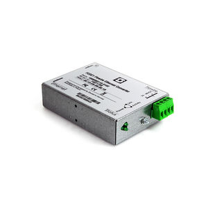
The Flowire Converter enables Ethernet to run on the same two wires as power, providing simpler cabling and opens up for longer cable hauls. The Flowire Converter is also capable of powering Ethernet devices attached to it, such as CCTV and IP intercom stations.
Contents
Additional documentation
For more documentation, please visit the Zenitel web page: https://www.zenitel.com/product/fcdc1
Installation
Overview
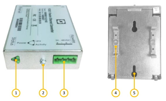
| 1 | Status indicators | Indicates status for power, link and activity |
| 2 | Ground connection | Ground connection for grounding of the unit |
| 3 | Flowire/Power ports | Connections for power and Flowire network |
| 4 | DIN mounting clips | Plastic clip to mount the Flowire Converter box to a DIN rail |
| 5 | Mounting holes |
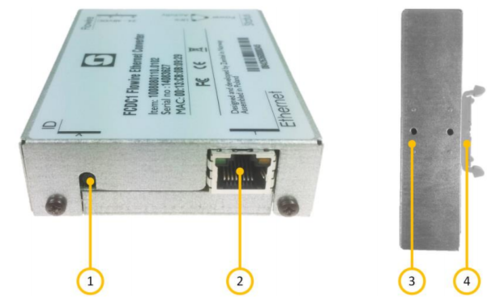
| 1 | Restore button | Button to reset the Flowire Converter to factory settings |
| 2 | Ethernet connection | Ethernet connection with power |
| 3 | Alt. position for DIN clips | |
| 4 | DIN mounting clips | Plastic clip to mount the Flowire Converter box to a DIN rail |
Placement
When used in an equipment rack, the Flowire Converter can be placed at any accessible location.
When installing more than one Flowire network in the same equipment rack,
precautions must be taken to reduce crosstalk between the networks.
Mounting
The Flowire Converter is a DIN-rail mounted device, and hence requires a DIN rail. The DIN rail shall be mounted securely to the equipment rack, and properly stabilized. The DIN clips on the Flowire Converter can be placed on either the side or the bottom, thus giving different mounting options.
Grounding
It is always good practice to ground the cabinet of equipment installed in racks. This ensures safety and good EMC. The grounding connection of the Flowire Converter should be connected to the equipment rack’s ground strip using a ground wire of at least 0.75 mm² (AWG 19).
Power Supply
The Flowire Converter can operate over a wide range of voltages. The voltage selected depends on the type of equipment connected to the Flowire network: 24 VDC: The Flowire Converter shall be powered by the 24VDC power supply Flowire Ex 120 or Flowire Ex 250 when used for the connection of Ex access panels. 48 VDC: The Flowire Converter shall be powered by the 48VDC power supply Flowire XP 120 or Flowire XP 240 when used for the connection of other Flowire Converter units.
  Other power supplies than the ones mentioned above shall not be used.


Connect the power supply to any one of the two Flowire/power ports of the Flowire Converter
using wires with a thickness of at least 1.5 mm² (AWG 15) and a length of at least 1 m.
Flowire Connection
The Flowire port shall be routed to a terminal block in the equipment rack. The Flowire connections shall be done in accordance with the Flowire manual A100K11422 Flowire Converter Configuration.
Use of Shielded Cable
When using shielded cable (for improved EMC when used in high-EMI areas) the shield should be attached to the chassis of the Flowire unit and the central rack.
Cabling in Ex Areas
The Ex access panels are connected to the central equipment rack using Ex certified 2-wire shielded cable. Flowire is used to extend the Ethernet connection and support power distribution on the 2-wire cabling infrastructure.
To support the Flowire interface, the central equipment rack must be equipped with a Flowire Converter (FCDC2).


