Difference between revisions of "EAPFX-1"
Rlorentzen (talk | contribs) (→Central connection) |
(→Accessories) |
||
| (45 intermediate revisions by 3 users not shown) | |||
| Line 11: | Line 11: | ||
* For single or dual systems (A and B systems) | * For single or dual systems (A and B systems) | ||
| − | The EAPFX-1 is a rugged access panel, developed for harsh offshore environments and hazardous areas. The antistatic plastic housing withstands corrosion from the most common corrosive gases and compounds found in this type of environment. The access panel features one fully programmable button, which can be used to manually initiate fire alarms, gas alarms or any other action in the Exigo system. The access panel is equipped with indicators to show the status of the power supply, call activity and whether a fault is present in the system. The access panel’s button features two independent status indicators | + | The EAPFX-1 is a rugged access panel, developed for harsh offshore environments and hazardous areas. The antistatic plastic housing withstands corrosion from the most common corrosive gases and compounds found in this type of environment. The access panel features one fully programmable button, which can be used to manually initiate fire alarms, gas alarms or any other action in the Exigo system. The access panel is equipped with indicators to show the status of the power supply, call activity and whether a fault is present in the system. The access panel’s button features two independent status indicators that shows the status of the button’s function. The access panel is fully digital, and connects to the Exigo system over a single-pair cable. The access panel is fully monitored to ensure detection of any fault which may compromise the system’s functionality. |
| + | |||
| − | |||
| − | |||
== Installation == | == Installation == | ||
===Overview - Front=== | ===Overview - Front=== | ||
| − | [[File: | + | [[File:EAPFX-1 overview front.PNG|left|350px|EAPFX-1]] |
<br style="clear:both;" /> | <br style="clear:both;" /> | ||
| + | {| border="1" | ||
| + | | align="center" style="background:#ffd400;" width="50pt" | 1 || align="left" | Hinge | ||
| + | |- | ||
| + | | align="center" style="background:#ffd400;" width="50pt" | 2 || align="left" | Button Label Area | ||
| + | |- | ||
| + | | align="center" style="background:#ffd400;" width="50pt" | 3 || align="left" | Lid Retention Screw | ||
| + | |- | ||
| + | | align="center" style="background:#ffd400;" width="50pt" | 4 || align="left" | Cable Glands | ||
| + | |- | ||
| + | | align="center" style="background:#ffd400;" width="50pt" | 5 || align="left" | Internal Microphone | ||
| + | |- | ||
| + | | align="center" style="background:#ffd400;" width="50pt" | 6 || align="left" | Status Indicators | ||
| + | |- | ||
| + | | align="center" style="background:#ffd400;" width="50pt" | 7 || align="left" | Function Indicators | ||
| + | |- | ||
| + | | align="center" style="background:#ffd400;" width="50pt" | 8 || align="left" | Function Button | ||
| + | |- | ||
| + | |} | ||
| + | <br> | ||
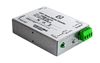
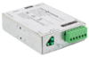
=== Connections === | === Connections === | ||
| + | [[File:EAPFX Overview Internal.PNG]] | ||
[[File:Turbine EX Connections.PNG]] | [[File:Turbine EX Connections.PNG]] | ||
| + | <br style="clear:both;" /> | ||
| + | {| border="1" | ||
| + | | align="center" style="background:#ffd400;" width="50pt" | 1 || align="left" | Accessory Interface | ||
| + | |- | ||
| + | | align="center" style="background:#ffd400;" width="50pt" | 2 || align="left" | Molded Electronics | ||
| + | |- | ||
| + | | align="center" style="background:#ffd400;" width="50pt" | 3 || align="left" | Flowire Connection | ||
| + | |- | ||
| + | |} | ||
| + | <br> | ||
| + | ----------- | ||
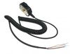
=== Flowire Connection === | === Flowire Connection === | ||
The EAPFX-1 features two Flowire connectors. Power and signal redundancy can be achieved by utilizing both Flowire connectors in an A-B system configuration. | The EAPFX-1 features two Flowire connectors. Power and signal redundancy can be achieved by utilizing both Flowire connectors in an A-B system configuration. | ||
| − | + | {{Note}} '''Do not connect more than 9 Ex Products to each central Flowire Converter.''' | |
<br> | <br> | ||
| − | + | {{Note}} '''Only use one of the Flowire connectors on each Ex product for each central Flowire Converter.''' | |
<br> | <br> | ||
| − | + | {{Note}} '''Load sharing power supply must be used for redundant cabling solutions.''' | |
| − | + | '''Consult Zenitel before implementing this type of solution.''' | |
| − | |||
| − | [[File:EX | + | [[File:EX Flowire 1.PNG|thumb|left|500px|The main board receives both power and Ethernet signals through two wires. You can connect either A or B for connection to the rest of the system, or both A and B, each to a separate server, in order to achieve redundancy.]] |
| + | <br style="clear:both;" /> | ||
| − | + | [[File:EX Flowire Single 1.PNG|thumb|left|500px|Connection of Flowire in a Single System.]] | |
| + | <br style="clear:both;" /> | ||
| − | [[File:EX Flowire | + | [[File:EX Flowire Redundant 1.PNG|thumb|left|500px|Connection Flowire in a Redundant A–B system.]] |
| + | <br style="clear:both;" /> | ||
| − | Connection | + | === Central Connection === |
| + | The central rack must contain: | ||
| + | * A Server | ||
| + | * A Flowire Converter ([[FCDC2]]) | ||
| + | * A '''24V''' Power Supply Unit (PSU) | ||
| + | In order to connect several Ex Products to one central FCDC2, you also need a terminal block. | ||
| − | [[File:EX Flowire | + | [[File:EX Flowire Central Server1.PNG|thumb|left|500px|Industrial Ex products connected to a central server.]] |
| + | <br style="clear:both;" /> | ||
| − | + | [[File:EX Flowire Redundant Servers1.PNG|thumb|left|500px|Industrial Ex products connected to two central servers in a redundant A-B system.]] | |
| − | + | <br style="clear:both;" /> | |
| − | |||
| − | |||
| − | |||
| − | |||
| − | |||
| − | |||
| − | |||
| − | |||
| − | |||
| − | |||
| − | |||
| − | [[File:EX Flowire Redundant Servers1.PNG | ||
| − | |||
| − | Industrial Ex products connected to two central servers in a redundant A-B system. | ||
| − | + | {{Note}} '''Only use 24VDC power supplies sold or recommended by Zenitel for Ex products.''' | |
=== Grounding === | === Grounding === | ||
| − | + | {{Note}} '''To establish explosion-proof protection, it is vital that the grounding of the panel is done according to the following instructions.''' | |
| − | |||
| − | |||
| − | + | All ground and shield cables from the central rack must be terminated on the ground sheet inside the main housing. Grounding must be done according to the IEC 60079-17 standard. | |
| − | + | The apparatus can not withstand the electrical strength test with 2 x Um 250V r.m.s. to earth according to clause 6.3.13 of IEC/EN 60079-11: 2011/2012 because the equipment has a connection to earth. | |
| − | |||
| − | + | === Cable Insertion === | |
| + | {{Note}} '''Only cables certified for use in explosive atmospheres shall be used.''' | ||
| + | <br> | ||
| + | {{Note}} '''Only Ex certified cable entries made from plastic shall be used.''' | ||
| + | <br> | ||
| + | {{Note}} '''The prescribed cable diameters and other guidelines for cable entries used shall be observed.''' | ||
| + | <br> | ||
| + | {{Note}} '''The relevant mounting directives for the cable entries used shall be observed.''' | ||
| + | <br> | ||
| + | {{Note}} '''When using cable entries with a degree of protection that differs from the IP protection of the''' | ||
| + | '''Ex Product (see Technical Specifications), the limiting IP protection level shall be adhered to.''' | ||
| + | <br> | ||
| + | {{Note}} '''When using cable entries with an ambient temperature range that differs from the ambient temperature''' | ||
| + | '''range of the panel or intercom (see Technical Specifications), the limiting temperature range shall be adhered to.''' | ||
| + | <br> | ||
| + | {{Note}} '''When using cable entries with impact resistance that differs from the impact resistance of the panel''' | ||
| + | '''or intercom, the limiting impact resistance shall be adhered to.''' | ||
| + | <br> | ||
| + | {{Note}} '''Cable entries must have ingress protection IP54 or higher.''' | ||
| + | <br> | ||
| + | {{Note}} '''Cable entries must be approved according to IEC 60079-0:2007 or EN 60079-0:2009 or''' | ||
| + | '''later versions of one of these standards.''' | ||
| + | <br> | ||
| + | {{Note}} '''In order to ensure the required minimum degree of protection, the cable entries must be tightened down securely.''' | ||
| + | <br> | ||
| + | {{Note}} '''Over-tightening can impair the degree of protection and damage the Ex Product.''' | ||
| + | <br> | ||
| + | {{Note}} '''When tightening the cap nut of a cable entry, a suitable tool shall be used to prevent the gland from twisting.''' | ||
| + | <br> | ||
| + | {{Note}} '''When using the Hummel M16 cable gland HSK-K-MZ-Ex included in the delivery, the following limiting factors apply:''' | ||
| + | * Lowest Temperature: -20°C | ||
| + | * Impact Resistance: 4J (low risk of mechanical danger) | ||
| − | + | == Restore Factory Defaults == | |
| + | * [[EAPFX Restore Factory Defaults|Restore Factory Defaults]] | ||
| − | + | == Dimensions == | |
| + | [[File:Eapfx-1 dimensions.PNG|left|upright=2.0|700px|alt=EAPFX-1.|EAPFX-1 dimensions]] | ||
| + | <br style="clear:both;" /> | ||
| − | + | == Accessories == | |
| − | |||
| − | |||
| − | + | {|{{SimpleTable}} | |
| − | + | |- | |
| − | + | !style="background:#FFFFFF;" width="200"|[[File:EMMAX-1H.JPG|100px|link=EMMAX-1H]] | |
| + | !style="background:#FFFFFF;" width="200"|[[File:FCDC2.jpg|100px|link=FCDC2]] | ||
| + | !style="background:#FFFFFF;" width="200"|[[File:FCDC-3.png|100px|link=FCDC3]] | ||
| + | |- | ||
| + | |style="text-align:center;"|[[EMMAX-1H]] | ||
| + | |style="text-align:center;"|[[FCDC2]] | ||
| + | |style="text-align:center;"|[[FCDC3]] | ||
| + | |- | ||
| + | |} | ||
| − | + | == Additional Documentation == | |
| − | + | For more documentation, please visit the Zenitel web page: https://www.zenitel.com/product/eapfx-1 | |
| − | |||
| − | |||
| − | |||
| − | |||
| − | |||
| − | |||
| − | |||
| − | |||
| − | |||
| − | |||
| − | |||
| − | |||
| − | |||
| − | |||
| − | |||
| − | |||
| − | |||
| − | |||
| − | |||
| − | |||
| − | |||
| − | |||
| − | |||
| − | |||
| − | |||
| − | |||
[[Category:Hardware]] | [[Category:Hardware]] | ||
| + | [[Category:Access Panels]] | ||
| + | [[Category:Ex Access Panels]] | ||
Latest revision as of 12:04, 6 February 2020

EXIGO Industrial Ex Access Panel
- Network access panel for explosive atmospheres
- Ex m b ib e IIC T4 Gb
- DSP for acoustic signal processing
- IP networking and power over Flowire technology
- One programmable button with individual label and status indicators
- Optional button protection covers
- Indicators for power, call and fault
- For single or dual systems (A and B systems)
The EAPFX-1 is a rugged access panel, developed for harsh offshore environments and hazardous areas. The antistatic plastic housing withstands corrosion from the most common corrosive gases and compounds found in this type of environment. The access panel features one fully programmable button, which can be used to manually initiate fire alarms, gas alarms or any other action in the Exigo system. The access panel is equipped with indicators to show the status of the power supply, call activity and whether a fault is present in the system. The access panel’s button features two independent status indicators that shows the status of the button’s function. The access panel is fully digital, and connects to the Exigo system over a single-pair cable. The access panel is fully monitored to ensure detection of any fault which may compromise the system’s functionality.
Contents
Installation
Overview - Front

| 1 | Hinge |
| 2 | Button Label Area |
| 3 | Lid Retention Screw |
| 4 | Cable Glands |
| 5 | Internal Microphone |
| 6 | Status Indicators |
| 7 | Function Indicators |
| 8 | Function Button |
Connections


| 1 | Accessory Interface |
| 2 | Molded Electronics |
| 3 | Flowire Connection |
Flowire Connection
The EAPFX-1 features two Flowire connectors. Power and signal redundancy can be achieved by utilizing both Flowire connectors in an A-B system configuration.
 Do not connect more than 9 Ex Products to each central Flowire Converter.
Only use one of the Flowire connectors on each Ex product for each central Flowire Converter.
 Load sharing power supply must be used for redundant cabling solutions.
          Consult Zenitel before implementing this type of solution.


Central Connection
The central rack must contain:
- A Server
- A Flowire Converter (FCDC2)
- A 24V Power Supply Unit (PSU)
In order to connect several Ex Products to one central FCDC2, you also need a terminal block.


Only use 24VDC power supplies sold or recommended by Zenitel for Ex products.
Grounding
To establish explosion-proof protection, it is vital that the grounding of the panel is done according to the following instructions.
All ground and shield cables from the central rack must be terminated on the ground sheet inside the main housing. Grounding must be done according to the IEC 60079-17 standard.
The apparatus can not withstand the electrical strength test with 2 x Um 250V r.m.s. to earth according to clause 6.3.13 of IEC/EN 60079-11: 2011/2012 because the equipment has a connection to earth.
Cable Insertion
Only cables certified for use in explosive atmospheres shall be used.
Only Ex certified cable entries made from plastic shall be used.
The prescribed cable diameters and other guidelines for cable entries used shall be observed.
The relevant mounting directives for the cable entries used shall be observed.
 When using cable entries with a degree of protection that differs from the IP protection of the
          Ex Product (see Technical Specifications), the limiting IP protection level shall be adhered to.
 When using cable entries with an ambient temperature range that differs from the ambient temperature
          range of the panel or intercom (see Technical Specifications), the limiting temperature range shall be adhered to.
 When using cable entries with impact resistance that differs from the impact resistance of the panel
          or intercom, the limiting impact resistance shall be adhered to.
Cable entries must have ingress protection IP54 or higher.
 Cable entries must be approved according to IEC 60079-0:2007 or EN 60079-0:2009 or
          later versions of one of these standards.
In order to ensure the required minimum degree of protection, the cable entries must be tightened down securely.
Over-tightening can impair the degree of protection and damage the Ex Product.
When tightening the cap nut of a cable entry, a suitable tool shall be used to prevent the gland from twisting.
 When using the Hummel M16 cable gland HSK-K-MZ-Ex included in the delivery, the following limiting factors apply:
           * Lowest Temperature: -20°C
           * Impact Resistance: 4J (low risk of mechanical danger)
Restore Factory Defaults
Dimensions

Accessories
|
|
|
|---|---|---|
| EMMAX-1H | FCDC2 | FCDC3 |
Additional Documentation
For more documentation, please visit the Zenitel web page: https://www.zenitel.com/product/eapfx-1