TKIE-1
Voip Intercom Module
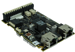
The TKIE-1 is the extended version of our Turbine Kit range. It offers the same high quality audio as the TKIS-x kit, but adds to the feature list with an extra RJ45 port for dual Ethernet connectivity, dual relays, and a header for easy connection of audio accessories. For high-power applications, the TKIE-1 may be complemented with the TA-10 Relay Module which offers 2 DPDT relays suited for high-voltage/high-current applications.
- IP station kit with extended functionality
- Dual RJ45 for Ethernet connectivity (with switch)
- Dual relays (DPDT)
- 6 configurable I/Os (input, output or LED-driving)
- Line-in/Line-out connectivity for connection to audio devices
- Header for connecting audio accessories
- Possibility for connecting high-power relay module (TA-10)
- High quality Turbine™ class output with 10W amplifier
- Full open duplex and digital noise reduction
Contents
Additional documentation
For more documentation, please visit the Zenitel web page: https://www.zenitel.com/product/tkie-1
Connections
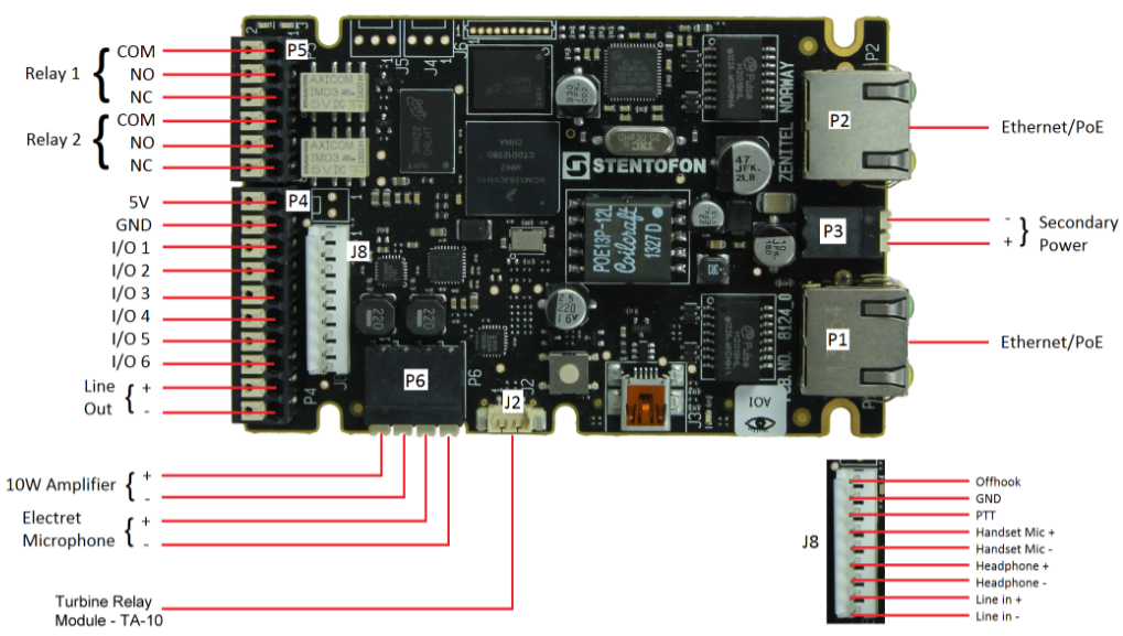
There are two RJ-45 ports located on the TKIE-1 that are used for PoE/LAN Ethernet connection.
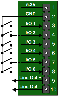
There are 6 I/O connection options for the TKIE-1. These connections are used as digital input (eg. form a closing contact), digital output (5V), or LED driving (20mA max) for connecting sensors, indicators or integration to other systems.
| Ethernet/Power | The TKIE-1 supports Power over Ethernet (PoE, IEEE 802.3 a-f) where power can be drawn from either the spare line or signal line.* |
| Secondary Power | If PoE in not available, the TKIE-1 can be powered from a 24-48 VDC local power supply.** |
| Relays | There are two Double Throw relay contacts with 60W switching power. COM, NO, NC contacts are provided. |
| Input/Output | 6 I/Os are available. Each I/O can be configured as either input, output, or LED driver. |
| Audio Line Out | A balanced 600 ohm audio line out with induction loop signal |
Note! Use cables crimped with ferrules for terminal block connectors
*If connected to two PoE-capable switches, only one of the ports will negotiate PoE; hence this is not a good solution for
power redundancy (switch failure might lead to a reboot). Instead a “dumb” PoE injector (spare-pair power) should be used
for the two Ethernet ports or a local 24 VDC local power backup.
**If used together with PoE the station can be powered by 24 VDC as a local power backup.
- When the TKIE-1 is connected to the network, its IP address is automatically obtained from a DHCP server or an IP address in the range 169.254.x.x will be assigned.
P1&P2 RJ45 PoE port for 10/100 Mbit Ethernet connection.
- The station can be powered from this port if the line supports Power over Ethernet (PoE).
P3 Secondary Power; 24-48VDC
P4 10-pin plug-on terminal for external connections.
- Pin 1 5.3V
- Pin 2 GND
- Pin 3 Button Input or LED Driver
- Pin 4 Button Input or LED Driver
- Pin 5 Button Input or LED Driver
- Pin 6 Button Input or LED Driver
- Pin 7 Button Input or LED Driver
- Pin 8 Button Input or LED Driver
- Pin 9 600 ohm balanced line out +
- Pin 10 600 ohm balanced line out -1
P5 6-pin plug-on terminal for external connections.
- Pin 1 COM relay 1
- Pin 2 NO relay 1
- Pin 3 NC relay 1
- Pin 4 COM relay 2
- Pin 5 NO relay 2
- Pin 6 NC relay 2
Note! Relay 1 is configured as output 7, and Relay 2 is configured as output 8!
P6 Loudspeaker & Electret microphone
- Pin 1 10W Speaker amplifier +
- Pin 2 10W Speaker amplifier -
- Pin 3 Electret Microphone +
- Pin 4 Electret Microphone -
J2 Turbine Relay Module - TA-10
Note! Relay 3 is configured as output 9, and Relay 4 is configured as output 10!
J8 Headset/Handset connector
- Pin 1 Offhook
- Pin 2 GND
- Pin 3 PTT
- Pin 4 Handset Mic Positive
- Pin 5 Handset Mic Negative
- Pin 6 Headphone Positive
- Pin 7 Headphone Negative
- Pin 8 Line In Positive
- Pin 9 Line In Negative
Input Connectors
P3 10-pin plug-on terminal for external connections.
- Pin 1 5.3V (max. 200mA current)
- Pin 2 GND
- Pin 3 Button Input or LED Driver
- Pin 4 Button Input or LED Driver
- Pin 5 Button Input or LED Driver
- Pin 6 Button Input or LED Driver
- Pin 7 Button Input or LED Driver
- Pin 8 Button Input or LED Driver
- Pin 9 600 ohm balanced line out +
- Pin 10 600 ohm balanced line out -
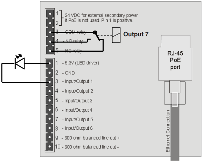
Output Connectors + 1 relay
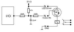
The extra relay for any of the 6 I/O pins is connected as shown:
Most general purpose P-Channel MOSFET's should work. Recommended example: BSS84
The 5,3V output can deliver 200mA current maximum
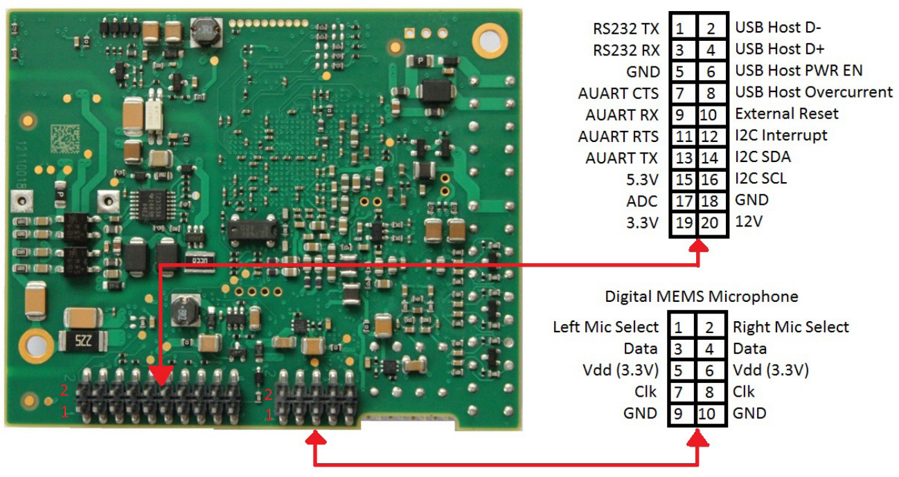
PCB - Rear
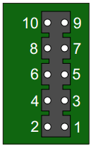
J6 10-pin terminal for digital MEMS Microphone
- Pin 1 Left mic select (Vdd)
- Pin 2 Right mic select (GND)
- Pin 3 Data
- Pin 4 Data
- Pin 5 Vdd 3.3V
- Pin 6 Vdd 3.3V
- Pin 7 CLK
- Pin 8 CLK
- Pin 9 GND
- Pin 10 GND
