ELTSI-1
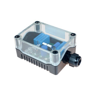
Exigo Industrial Line End Transponder
- Loudspeaker line end transponder
- Powered from and communicates over the loudspeaker lines
- Small and simple to install
- Rugged and weatherproof housing
The ELTS I-1 line end transponder is designed for use on ships and offshore environments. Hence, the construction is very robust and can handle mobile environments as well as stationary, temperature controlled rooms.
The line end transponder ensures reliable monitoring of the loudspeaker lines. Where impedance measurements may result in an erroneous report of a broken line, the line end transponder will always report the correct health of the loudspeaker loop.
Each amplifier can have a total of 10 LETs (ELTSI-1) divided among the channels.
Several ELTSI-1 on the same amplifier channel is making it possible to branch out the loudspeaker loops.
Contents
Installation
Overview
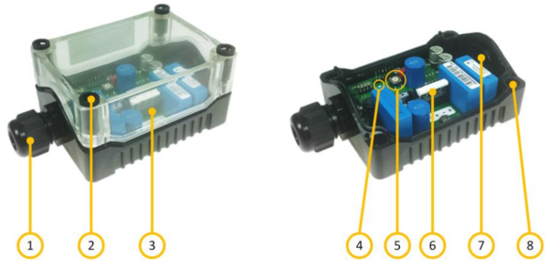
| 1 | Cable Gland |
| 2 | Lid Retention Screw |
| 3 | Transparent Lid |
| 4 | Status Indicator LED |
| 5 | Address Selector |
| 6 | Connection Terminals |
| 7 | Cable Gland Entry |
| 8 | Mounting Holes |
Placement
The ELTSI-1 Line End Transponder is a rugged device, intended for use in rugged environments. It can therefore be mounted in protected areas, or exposed areas with heavy rain and pollutants. The unit should be placed in such a way that the status indicator can be easily seen after installation. This will ease the maintenance of the system.
 The ELTSI-1 unit shall not be mounted in areas classified as Ex areas. If a line end transponder is
          required in such areas, it must be installed in a flame-proof enclosure (Ex d) according to IEC 60079.
Setting the Address
The address of the unit should be set before mounting as this will make the operation easier. The address is set using the address selector.
- Remove the lid by carefully unscrewing the four lid retention screws.
- Use a small screwdriver to turn the address selector (small arrow on the wheel) to a number between 1 and 10. The address of the unit shall be set according to the system plan.
Connecting the Terminals
If the cable entry is still covered, screw in the cable gland body until it punches the cover out to make a hole for cable access.
- Thread the cable through the cable gland and cable entry of the unit.
- Connect the loudspeaker line to either of the two spring loaded connection terminals.
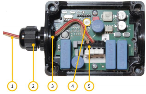
| 1 | Cable Line |
| 2 | Cable Gland |
| 3 | Cable Entry |
| 4 | Address Selector |
| 5 | Connection Terminals |
Mounting
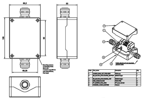
The ELTSI-1 unit must be mounted on a flat surface using the four screw holes. These holes are located under the lid retention screws.
If the unit is mounted inline, an extra cable gland must be mounted for the extending cable. When mounting inline, make sure to be consistent when connecting the cable to the terminals.
The screws used to mount the unit must be suitable for the purpose, and have a head diameter of not more than 6.6 mm. The diameter of the screw itself must be not be more than 4 mm. The ELTSI-1 box will “consume” 7 mm of the screw’s length. Depending on the type of material on which the device is mounted, use an M3.5 socket/slotted screw or a pan head wood screw of diameter 3.5 mm.
Complete the installation by securing the lid again, using the four lid retention screws.
Do not use too much force when tightening the four lid retention screws. These are made of plastic and can be easily broken if powered screwdrivers are used.
Status Indication LED
When the device is connected and properly powered from the amplifier, it will periodically signal its status via the small green LED indicator. The LED indicator can flash in various patterns as follows:
After Reset or Power-Up:
3 short flashes every 10 seconds (sequence is repeated 2 or 3 times) followed by 1 long flash plus the numerical address of the unit in short flashes, e.g. 5 short flashes indicates that the unit has address number 5.
This is repeated until the ELTSI-1 receives a request from the amplifier.
After Contact with Amplifier:
1 short flash every 10 seconds. The amplifier will send a new request to the ELTSI-1 circa every 15 seconds. If the request from the amplifier is not received within 60-70 seconds, the LED will emit 2 short flashes every 10 seconds followed by 1 long flash plus the numerical address of the unit in short flashes.
This is repeated until the ELTSI-1 receives a request from the amplifier.
Use of LET units must be enabled in EMT or locally on the amplifier before the ELTSI-1 becomes operational and the output must be calibrated successfully using the amplifier.
Dimensions
Additional Documentation
For more documentation, please visit the Zenitel web page: https://www.zenitel.com/product/eltsi-1


