Difference between revisions of "EMBR Mounting Boxes"
(→Using the EMBR Mounting Boxes) |
(→Using the EMBR Mounting Boxes) |
||
| Line 10: | Line 10: | ||
== Using the EMBR Mounting Boxes == | == Using the EMBR Mounting Boxes == | ||
| − | The image below show the EMBR-1 back-box. The EMBR-2 back-box is identical, except it has room for two panels. If more than two panels are to be installed in the same back-box, the EMBR-6 kit can be used to join several boxes together. | + | The image below show the EMBR-1 back-box. The EMBR-2 back-box is identical, except it has room for two panels. <br> |
| + | If more than two panels are to be installed in the same back-box, the EMBR-6 kit can be used to join several boxes together. | ||
[[File:EMBR Mounting1.PNG|left|600px|EMBR]] | [[File:EMBR Mounting1.PNG|left|600px|EMBR]] | ||
Revision as of 12:43, 4 May 2018
Mounting Box for ECPIR, EAPIR and EBMDR-8 Panels
- For desktop or on-wall mounting
- Boxes can be joined to accommodate up to 5 panels using the EMBR-6 kit
- Indoor use
Contents
Using the EMBR Mounting Boxes
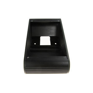
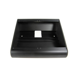
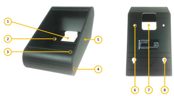
The image below show the EMBR-1 back-box. The EMBR-2 back-box is identical, except it has room for two panels.
If more than two panels are to be installed in the same back-box, the EMBR-6 kit can be used to join several boxes together.
| 1 | Cable entry hole |
| 2 | Mounting holes |
| 3 | Screw hole for panel |
| 4 | Side wall retention |
| 5 | Side wall |
| 6 | Mounting holes |
| 7 | Cable entry hole |
| 8 | Mounting hole |
Desktop Mounting
When used for desktop mounting, the accompanying rubber feet should be mounted on the bottom of the mounting box. These will prevent the unit from sliding around.
The cable, or cables, to the central equipment rack(s) must be pulled into the mounting box and plugged into the access panel before the access panel is secured to the mounting box with the 4 accompanying screws.
On-wall Mounting
When used for wall mounting, the mounting box should be mounted to the wall using the holes at the bottom of the unit. The mounting box should be mounted with the thickest end down so that the access panel is inclined towards the operator. The box can also be mounted the other way around, if this is desired in the installation.
The cable, or cables, to the central equipment rack(s) must be pulled into the mounting box and plugged into the access panel before the access panel is secured to the mounting box with the 4 accompanying screws. The cable(s) shall either enter the box through a hole in the wall or through a proper cable duct.
Combining Boxes
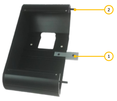
Several mounting boxes can be joined using the EMBR-6 kit. This kit consists of two “spring rods”, a metal joint and two screws. The side panels facing the box joint must be removed, and the “spring rods” and the metal joint must be inserted into one of the joining boxes, as shown in the image below. The second box is then inserted on the “spring rods” and metal joint. Finally the two screws are used to fasten the metal joint, securing the two boxes together.
| 1 | Connecting plate |
| 2 | Connecting pins |
The “spring rods” are quite tight, and it may require some force to get them in place.
A small hammer can be used for this purpose.
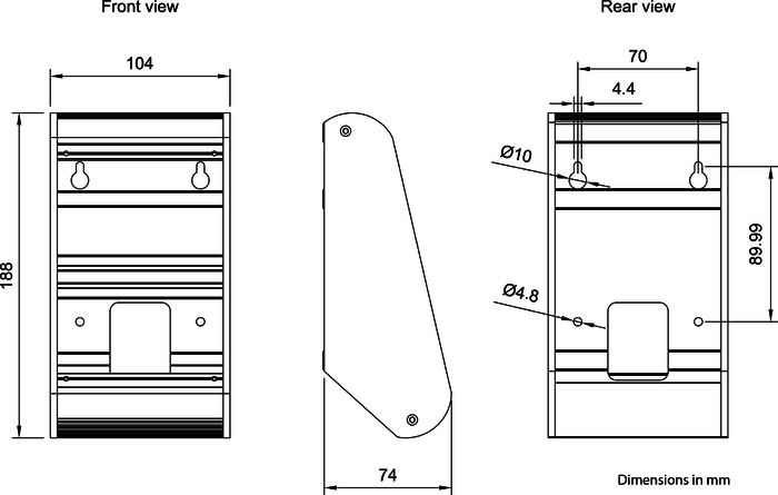
Dimensions EMBR-1
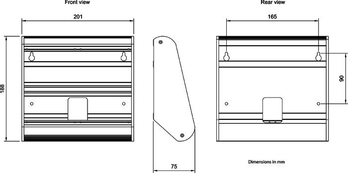
Dimensions EMBR-2
Additional Documentation
For more documentation regarding EMBR1, please visit the Zenitel web page: https://www.zenitel.com/product/embr-1
For more documentation regarding EMBR-2, please visit the Zenitel web page: https://www.zenitel.com/product/embr-2
