Difference between revisions of "ENA2100-AC"
(→Overview - Back) |
|||
| Line 40: | Line 40: | ||
<br> | <br> | ||
----------- | ----------- | ||
| − | |||
== Overview - Back == | == Overview - Back == | ||
Revision as of 12:33, 14 December 2018
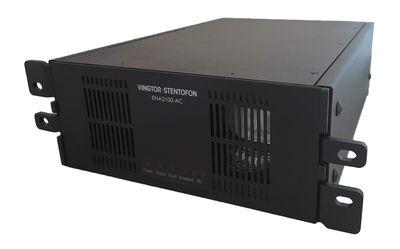
Exigo Network Amplifier
- 2 x 100 watt continuous GA effect
- Power efficient class D technology
- 115/230 VAC power
- Redundant Ethernet connections
- Digital audio processing
- Loudspeaker line monitoring
- Line input
- Embedded tick tone generator
- 2 configurable control outputs (24 VDC ±10%, 200 mA, monitored)
- 2 configurable control inputs
The Exigo Network Amplifier is designed for use in marine, offshore and other demanding environments. The amplifier utilizes state-of-the-art class D amplifier technology to ensure high power efficiency and superb audio quality for two audio channels which can be loaded with up to 100W each.
The Exigo Network Amplifier is part of the Exigo PA/GA system, which is based on standard Ethernet network and digital processing. Each amplifier has two network connections, allowing for redundant cabling between the amplifier and the network.
Using standard network equipment also allows for a much wider selection of standard network equipment. The amplifier is also compatible with the Alphacom platform, allowing for advanced communication systems with both intercoms and PA.
The complete amplifier is self-monitoring and this includes advanced monitoring of the speaker lines and internal system. The audio output channels can be monitored for line faults such as shorts, ground faults and large load changes.
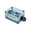
In addition, up to 10 intelligent Line End Transponders (ELTSI) can be placed on the speaker lines for additional accuracy in the line monitoring. The amplifier also monitors control inputs, power supplies, temperature, network connections and every other components required for operation of essential services. Faults will be reported to the system controller, but will also be indicated locally on the amplifier.
The amplifier’s configurable control inputs/outputs and audio inputs can be used to trigger various activities in the system.
The audio line input can also be configured in a "hardware bypass" mode where audio on the line input will be forwarded to the 100V channels directly, even when no server is available. This allows for additional redundancy and functions to be built around this amplifier.
Contents
Installation
Overview - Front
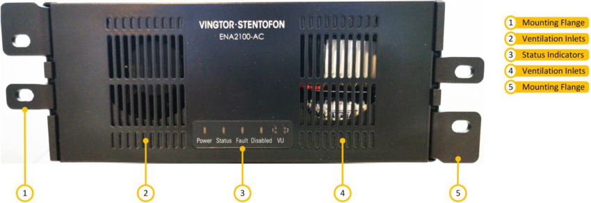
| 1 | Mounting Flanges | The mounting flanges are used to mount the unit in 19” equipment racks with 2HU in double configuration. |
| 2 | Ventilation Inlets | The ventilation inlets should be kept free of obstacles and dust. Fans control the airflow based on internal temperature. |
| 3 | Status Indicators | The status indicators are used to display the status of important parameters like power supply and faults. There is also a VU indicator for channel 1 and channel 2. |
Overview - Back
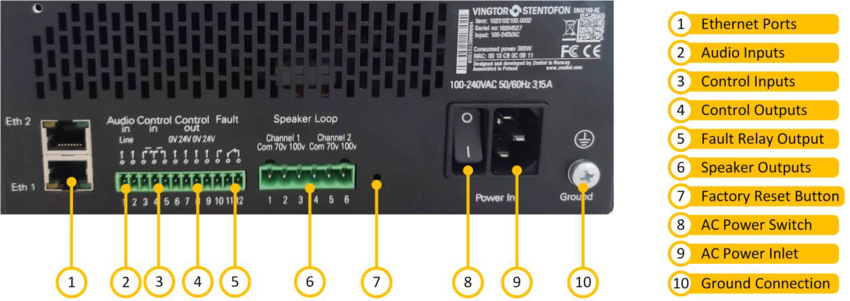
| 1 | Ethernet Ports | Redundant Ethernet connections for audio and control data. |
| 2 | Audio Inputs | Microphone and line-in audio inputs for microphones or external audio sources. |
| 3 | Control Inputs | 2 configurable control inputs. Each input is activated by closing the loop between the two terminals. |
| 4 | Control Outputs | 2 configurable control outputs. Each is made of a 24VDC signal. The 24VDC can source max 200mA and has overcurrent protection. |
| 5 | Fault Relay Output | A switching relay (NO, NC & COM) kept in the active position between COM and NO as long as no faults are present in the device. |
| 6 | Speaker Outputs | 100 and 70 volts outputs per channel. |
| 7 | Factory Reset Button | To reset the amplifier to factory default settings: Insert a straightened paper clip or similar device into the hole to press the reset button and hold for 7 to 8 seconds while powering up the amplifier. |
| 8 | AC Power Switch | Power switch for AC power. |
| 9 | AC Power Inlet | AC power inlet for 110 to 230 VAC. The power inlet has a V-Lock mechanism for a secure connection. |
| 10 | Ground Connection | Ground connection for grounding of the unit. This is connected in parallel with the ground connection in the AC power inlet. |
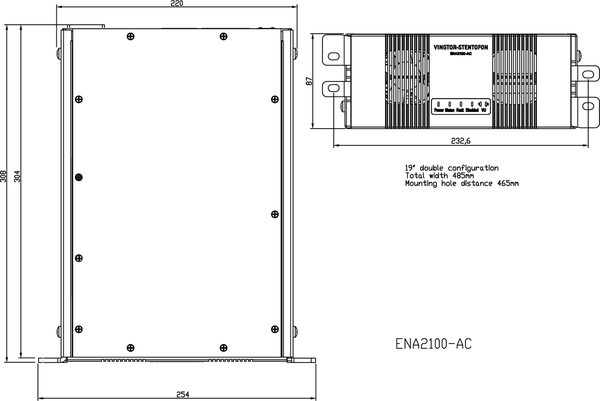
Dimensions
Accessories
|
|---|
| ELTSI-1 |
Additional Documentation
For more documentation, please visit the Zenitel web page: https://www.zenitel.com/product/ena2100-ac
