Difference between revisions of "Exigo Flowire Guidelines"
(→Flowire CCo) |
|||
| Line 57: | Line 57: | ||
For point-to-point link between two Flowires, it does not matter. | For point-to-point link between two Flowires, it does not matter. | ||
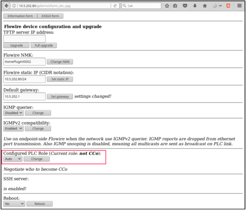
| + | ==== Configured PLC Role ==== | ||
| + | From Flowire SW version 4.1.3.10 and later, it has been possible to configure CCo mode under the section Configured PLC Role in the device web interface. | ||
| + | |||
| + | There is a choice of three modes: | ||
| + | * '''auto''': Default - Negotiate who is to be CCo. | ||
| + | * '''CCo''': Force this Flowire to be CCo. Only one Flowire in the cluster can be forced to be CCo! | ||
| + | * '''not CCo''': This Flowire is never the CCo. | ||
=== Wiring, Connection and Shielding with Flowire === | === Wiring, Connection and Shielding with Flowire === | ||
Revision as of 09:13, 20 December 2017
This article aims to describe the recommended use of the Flowire Converter with the Exigo PA/GA system.
Contents
How to use Flowire
General
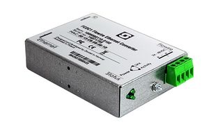
The Flowire Converters, FCDC1 and FCDC2, enable Ethernet to run on the same two wires as power, providing simpler cabling and opening up for longer cable hauls.
The FCDC1 is capable of powering Ethernet devices attached to it, such as IP PA panels with PoE Mode B. FCDC2 does not forward power to its Ethernet port.
Flowire can be used to support redundant connections, such as a PA panel connected to both main switches in an AB system. This requires a one-to-one connection to each switch.
Flowire also supports star configuration, meaning one-to-many. This configuration does not support redundancy. Different Flowire clusters must have separate Network Management Keys (NMK) to avoid detrimental results from crosstalk.
Flowire units meant to communicate with each other must use the same NMK. A cluster is here defined as all the Flowire units connected to one power supply.
Different Flowire clusters must have separate Network Management Keys (NMK) to avoid detrimental results from crosstalk.
Flowire units meant to communicate with each other must use the same NMK. A cluster is here defined as all the Flowire units connected to one power supply.
In a redundant system, make sure the primary link between rack A and rack B does not utilize Flowire.
Power
Flowire Converters operate on 24VDC or 48VDC.
- 48VDC is required to power IP POE products, such as PA panels via the Ethernet port. Minimum voltage at remote Flowire unit to obtain PoE is 40VDC. Minimum voltage at EAPFX-1 and EAPFX-6 access panel is 18VDC.
- 24VDC is required to power Vingtor-Stentofon Ex panels: EAPFX-1 and EAPFX-6. These panels do not tolerate 48VDC.
Only FCDC1 forwards power via the Ethernet port. If this is not required, use FCDC2. Always use FCDC2 for connecting to the switch, as FCDC1 would forward power to the switch port.
Rapid Spanning Tree Protocol (RSTP)
Flowire can be used to connect redundant access panels. STP or RSTP is used in the switches and panels to prevent loops and other issues in the network.
RSTP should be enabled to get the fastest response times if changes occur on the network.
Under ideal conditions, a panel utilizing RSTP can switch from its main connection to its backup connection in 10-20 ms if the main connection is lost. If a panel does not have a redundant connection, RSTP should not be enabled on the panel.
Note that in a redundant system, a panel cannot serve as a link between system A and system B (switch-to-switch) if RSTP is enabled. Panels with RSTP enabled will not forward traffic from one Ethernet interface to the next.
Ex panels (EAPFX) do not have RSTP capabilities, and will have longer switchover times than regular IP panels using RSTP.
After activating RSTP, connection to the panel must go through a switch. Direct connection from the PC to the panel will no longer work.
IGMP Settings
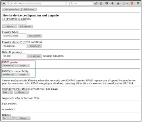
It is possible to configure IGMP settings in the Flowire web interface. The general guidelines are:
- Never enable IGMPv2 compatability mode on the Flowire unit closest to the switch.
- For device-side Flowire units, this setting is irrelevant, unless they are in a star configuration (see this section).
- Never enable IGMP querier on Flowire when using a managed switch in the system.
For more info on IGMP settings, go to our wiki page on the subject.
Flowire CCo
One of the Flowires in a cluster must be the CCo - Central Coordinator. CCo is essentially a bus master.
By default, the Flowires automatically negotiate among themselves who is to be CCo.
By cluster we mean Flowires on a physical bus that share an NMK - Network Membership Key.
If several NMKs are used, each "NMK-group" will be a cluster with its own CCo. (The HomePlug term for cluster is AVLN.)
But if there are more than two Flowires in a cluster, it can make a difference which Flowire is the CCo.
If the CCo Flowire is lost, then the communication in the whole cluster will stop for several seconds until a new CCo is agreed upon.
Therefore it is best that a network-side Flowire is CCo, so that an endpoint-side Flowire out in the field can be lost without affecting the rest of the cluster.
For point-to-point link between two Flowires, it does not matter.
Configured PLC Role
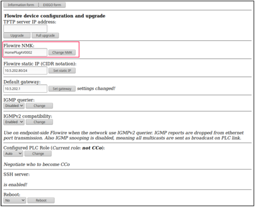
From Flowire SW version 4.1.3.10 and later, it has been possible to configure CCo mode under the section Configured PLC Role in the device web interface.
There is a choice of three modes:
- auto: Default - Negotiate who is to be CCo.
- CCo: Force this Flowire to be CCo. Only one Flowire in the cluster can be forced to be CCo!
- not CCo: This Flowire is never the CCo.
Wiring, Connection and Shielding with Flowire
Flowire uses a high frequency signal for data communication, and could potentially interfere with other systems.
To avoid this:
- Use a twisted, shielded pair for cabling
- Separate the different pairs/cables/links as much as possible
- The cable between the PSU and the Flowire unit should not be shorter than 50 cm
- All Flowires should be separated by at least 5 cm
- The cable shield should only be connected to ground in one place, on the rack side
- Redundant Flowire connections must be powered on separate electrical circuits
Network Configuration
Switch Configuration
Always use managed switches for redundant Flowire connections (panels or other IP products connected to two Exigo systems for backup purposes).
Flowire units in redundant configurations need to be configured as a trunk on the switch, with native VLAN 1.
Where available, such as on advanced Cisco switches, storm control should be implemented to block rogue ports in a network storm if spanning-tree fails.
The storm control will block the ports as soon as it reaches the configured threshold on the port, and resume to forwarding states after it has returned below the safe level.
Cisco Switch configuration for trunk port:
- interface FastEthernet1/1
- description FLOWIRE LINK
- switchport mode trunk
- switchport nonegotiate
- storm control broadcast level pps 350 150
- storm control multicast level pps 350 150
- storm control action shutdown
- spanning-tree guard loop
Flowire units without a redundant link is treated as an end point and should be configured as an access port with portfast. When portfast is configured on the port it will always be in forwarding state.
Cisco switch configuration for access port:
- interface FastEthernet1/2
- description FLOWIRE ACCESS PORT
- switchport mode access
- switchport nonegotiate
- spanning-tree portfast
Network Management Key (NMK) Configuration
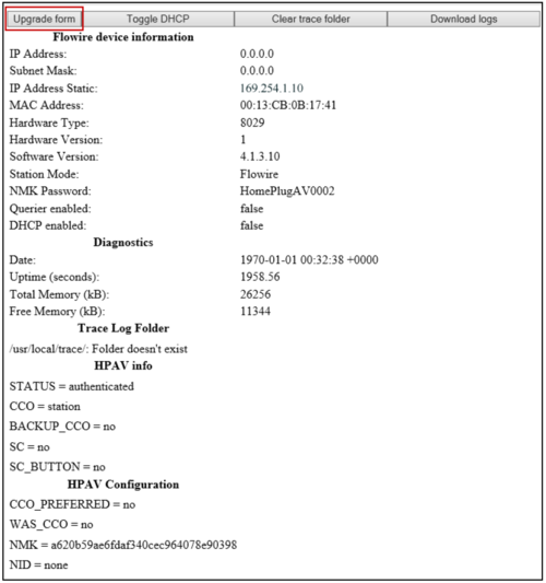
The NMK is configured in the Flowire’s web interface.
To set a new NMK password:
1. Log into the Flowire device by entering its IP address in a web browser. The default IP address is 169.254.1.10.
2. Click the Upgrade form button
3. Enter a new password in the Flowire NMK field
4. Click Change NMK
The NMK Password must be between 8 and 64 characters long, and is case sensitive.
It is good practice to label the Flowire device with the new NMK.
Default NMK: HomePlugAV0123
To ensure correct operation Flowire should use static IPs in Exigo system.
Flowire Configurations
One-to-One Connection
A one-to-one connection can be wired in 4 different ways in an Exigo system.
Option 1: Single Connection - 2 Flowire Units
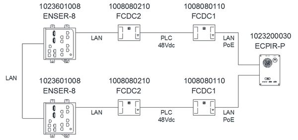
When no redundancy is required, a single link using two Flowires is used - one FCDC2 in the rack, and one FCDC1 at the panel end. If the single connection fails, communication with the panel will be lost.
When using more than one Flowire connection (when supporting more than one panel via Flowire), each connection must utilize a separate NMK and power supply.
If it is not desired to power the panel via the Ethernet port, use FCDC2 at the panel end and connect a power supply to the panel.
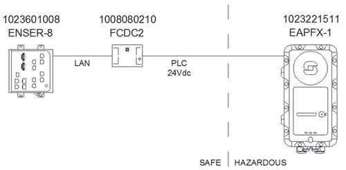
Option 2: Single Connection Ex Panel - 1 Flowire Unit
When no redundancy is required on an Ex panel (EAPFX-1 or EAPFX-6), a single link using one FCDC2 in the rack is sufficient. Ex panels have Flowire technology integrated on the main board. If the single connection fails, communication with the panel is lost.
When using more than one Flowire connection (when supporting more than one panel via Flowire), each connection must utilize a separate NMK and power supply.
Ex panels must be powered via the Flowire unit in the rack using 24VDC power supply only.
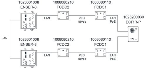
Option 3: Redundant Connections - 4 Flowire Units
When redundancy is required, use two Flowire links, one for system A and one for system B, consisting of two Flowire units each. One FCDC2 in each rack is connected to one FCDC1 each at the panel end. Each FCDC1 is connected to one Ethernet port on the panel.
If the system is configured correctly, one of the Flowire connection can be lost without losing communication with the panel. Switchover time will depend on whether or not the panel is configured to use RSTP.
Each connection should use a separate NMK, one for the A system and one for the B system.
When using more than one Flowire connection from each rack (when supporting more than one panel via Flowire), each connection must utilize a separate NMK and power supply.
If it is not desired to power the panel via the Ethernet port, use FCDC2 at the panel end and connect a power supply to the panel.
 The two Flowire units at the panel end could in theory be replaced by one Flowire unit.
          This is not recommended as each connection would be vulnerable to short circuiting on the other connection. It would, in practice, constitute a single connection between two systems, using only one NMK.
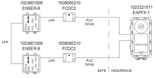
Option 4: Redundant Connections Ex Panel - 2 Flowire Units
When redundancy is required on an Ex panel (EAPFX-1 or EAPFX-6), two links using one FCDC2 in each rack is sufficient. Ex panels have Flowire technology integrated on the main board.
If the system is configured correctly, one Flowire connection can be lost without losing communication with the panel. Switchover time should be 7-10 seconds. RSTP is not supported on Ex panels.
The Flowire units in each rack and the Flowire unit in the Ex panel must have the same NMK and power supply.
When using more than one Flowire connection from each rack (when supporting more than one panel via Flowire), each connection must utilize a separate NMK and power supply.
Ex panels must be powered via the Flowires in the racks using 24VDC power supplies only.
Note: Make sure the primary link between rack A and rack B does not utilize Flowire.
Star Configuration
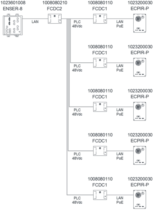
In order to save space and/or reduce the number of Flowire units in a system, it is possible to connect up to 10 Flowire units in a “star configuration” where 1 Flowire unit in the rack is connected to the switch,
and the other 9 are connected to this Flowire unit, usually via a patch panel.
This configuration is not recommended for software version 4.1.3.9 or earlier.
PLC = Power Line Communication
The star configuration cannot be redundant. In an A-B system, a star configuration can only be connected to either the A or the B system.
CCo Settings for Star Configuration
In the Flowire web interface, each Flowire unit has a setting for CCo (Central Coordinator). In every Flowire network, there is always one CCo, but this is, by default, automatically selected.
If the CCo should fail, another Flowire unit on the network is automatically selected to be the CCo. In a star configuration, in order to optimize availability, it is recommended to always configure the FCDC2 in the rack to be CCo.
Due to its location, it is least likely to suffer damage; and if this Flowire unit fails, the star configuration will not function in any case, whether or not it is the CCo, as all other Flowire units are routed through it.
In order for the FCDC2 in the rack to be configured as a CCo, it is necessary to configure the device-side Flowire units to be not CCo.
After changing CCo settings, the Flowire unit needs to be rebooted.
For more information, go to our wiki page on this subject.
IGMP Settings for Star Configuration
IGMP Querier
In order to secure the reliability of multicast handling in Flowire star configurations, the network should have an active IGMP querier.
If the core network is an unmanaged switch with no IGMP querier, it is possible to enable an IGMP querier in Flowire.
The setting is in the Flowire web interface, and activates an IGMPv3 querier. It is recommended to enable IGMP querier on the Flowire unit closest to the switch.
If the core network has an IGMP querier, do not enable IGMP querier in any of the Flowire units.
IGMPv2 Compatability
Current versions of Cisco industrial switches only handle IGMPv2. Therefore, the Cisco switch should be the IGMP querier, forcing the system to IGMPv2 reporting.
In systems where the network has an IGMPv2 querier, and there are several devices in a star configuration, the IGMPv2 compatibility mode must be enabled in the device-side/endpoint Flowire units.
This setting is available in Flowire SW version 4.1.3.10 and later.
- IGMPv2 compatibility mode must never be enabled on the Flowire unit closest to the switch
- IGMPv2 compatibility mode must be enabled on the device-side/endpoint Flowire units
Flowire CCo
Information can be found here.
Additional Documentation
For more information, go to our wiki page on this subject.
