Difference between revisions of "EAPII-1"
(→Overview - Front) |
|||
| (33 intermediate revisions by 3 users not shown) | |||
| Line 1: | Line 1: | ||
| + | [[File:EAPII-1.jpg|thumb|alt=EAPII-1.|EAPII-1]] | ||
| + | '''Exigo Industrial Access Panel''' | ||
* Network access panel for industrial environments | * Network access panel for industrial environments | ||
| Line 8: | Line 10: | ||
* For single or dual systems (A and B systems) | * For single or dual systems (A and B systems) | ||
| − | The EAPII-1 is a rugged access panel, developed for harsh industrial environments. The plastic housing withstands | + | |
| − | corrosion from the most common corrosive gasses and compounds found in this type of environment. The access panel | + | The EAPII-1 is a rugged access panel, developed for harsh industrial environments. The plastic housing withstands corrosion from the most common corrosive gasses and compounds found in this type of environment. |
| − | features one fully | + | |
| − | in the Exigo system. | + | The access panel features one fully programmable button, which can be used to manually initiate fire alarms, gas alarms or any other action in the Exigo system. |
| − | The access panel is equipped with indicators to show the status of the power supply, call activity and whether a fault is | + | |
| − | present in the system. The access panel’s button features two independent status indicators, which shows the status of | + | The access panel is equipped with indicators to show the status of the power supply, call activity and whether a fault is present in the system. The access panel’s button features two independent status indicators, which shows the status of the button’s function. |
| − | the button’s function. | + | |
| − | The access panel is fully digital, and connects to the Exigo system over standard Ethernet. Two Ethernet ports are available | + | The access panel is fully digital, and connects to the Exigo system over standard Ethernet. Two Ethernet ports are available in order to facilitate redundant cabling and connection to A and B system. The access panel is fully monitored to ensure detection of any fault which may compromise the system’s functionality. |
| − | in order to | + | |
| − | detection of any fault which may compromise the | + | |
| + | ==Installation== | ||
| + | === Overview - Front === | ||
| + | [[File:EAPII-1 overview front.PNG|left|350px|EAPII-6]] | ||
| + | <br style="clear:both;" /> | ||
| + | {| border="1" | ||
| + | | align="center" style="background:#ffd400;" width="50pt"| 1 || align="left" | Hinge | ||
| + | |- | ||
| + | | align="center" style="background:#ffd400;" width="50pt"| 2 || align="left" | Button Label Area | ||
| + | |- | ||
| + | | align="center" style="background:#ffd400;" width="50pt"| 3 || align="left" | Lid Retention Screw | ||
| + | |- | ||
| + | | align="center" style="background:#ffd400;" width="50pt"| 4 || align="left" | Cable Glands | ||
| + | |- | ||
| + | | align="center" style="background:#ffd400;" width="50pt"| 5 || align="left" | Internal Microphone | ||
| + | |- | ||
| + | | align="center" style="background:#ffd400;" width="50pt"| 6 || align="left" | Status Indicators | ||
| + | |- | ||
| + | | align="center" style="background:#ffd400;" width="50pt"| 7 || align="left" | Function Indicators | ||
| + | |- | ||
| + | | align="center" style="background:#ffd400;" width="50pt"| 8 || align="left" | Cover mounting | ||
| + | |- | ||
| + | | align="center" style="background:#ffd400;" width="50pt"| 9 || align="left" | Function button | ||
| + | |- | ||
| + | |} | ||
| + | <br> | ||
| + | ----------- | ||
| + | |||
| + | ===Overview - Internal=== | ||
| + | [[File:EAPII-6 Overview Internal.PNG|left|500px]] | ||
| + | <br style="clear:both;" /> | ||
| + | {| border="1" | ||
| + | | align="center" style="background:#ffd400;" width="50pt" | 1 || align="left" | Processor Board | ||
| + | |- | ||
| + | | align="center" style="background:#ffd400;" width="50pt" | 2 || align="left" | Mounting for TA-10 | ||
| + | |- | ||
| + | | align="center" style="background:#ffd400;" width="50pt" | 3 || align="left" | I/O connections | ||
| + | |- | ||
| + | | align="center" style="background:#ffd400;" width="50pt" | 4 || align="left" | TA-10 Relay Board | ||
| + | |- | ||
| + | | align="center" style="background:#ffd400;" width="50pt" | 5 || align="left" | Relay Connections | ||
| + | |- | ||
| + | | align="center" style="background:#ffd400;" width="50pt" | 6 || align="left" | Fuses | ||
| + | |- | ||
| + | | align="center" style="background:#ffd400;" width="50pt" | 7 || align="left" | Ethernet Port 1 | ||
| + | |- | ||
| + | | align="center" style="background:#ffd400;" width="50pt" | 8 || align="left" | Ethernet Port 2 | ||
| + | |- | ||
| + | | align="center" style="background:#ffd400;" width="50pt" | 9 || align="left" | TA-10 Connection | ||
| + | |- | ||
| + | | align="center" style="background:#ffd400;" width="50pt" | 10 || align="left" | Accessory Interface | ||
| + | |- | ||
| + | | align="center" style="background:#ffd400;" width="50pt" | 11 || align="left" | Relay Connections | ||
| + | |- | ||
| + | |} | ||
| + | <br> | ||
| + | |||
| + | == Connections == | ||
| + | [[File:EAPII Connections.JPG|thumb|left|500px|EAPII-1 Connections]] | ||
| + | <br style="clear:both;" /> | ||
| + | |||
| + | == Restore Factory Defaults == | ||
| + | * [[EAPII Restore Factory Defaults|Restore Factory Defaults]] | ||
| + | |||
| + | == Dimensions == | ||
| + | [[File:EAPII-1 Dimensions.PNG|left|upright=2.0|600px|alt=EAPII-1.|EAPII-1 dimensions]] | ||
| + | <br style="clear:both;" /> | ||
| + | |||
| + | == Accessories == | ||
| + | |||
| + | {|{{SimpleTable}} | ||
| + | |- | ||
| + | !style="background:#FFFFFF;" width="200"|[[File:EMMAI-2H.JPG|100px|link=EMMAI-2H]] | ||
| + | !style="background:#FFFFFF;" width="200"|[[File:TA-10.jpg|100px|link=TA-10]] | ||
| + | !style="background:#FFFFFF;" width="200"|[[File:Ta 23.PNG|100px|link=TA-23]] | ||
| + | |- | ||
| + | |style="text-align:center;"|[[EMMAI-2H]] | ||
| + | |style="text-align:center;"|[[TA-10]] | ||
| + | |style="text-align:center;"|[[TA-23]] | ||
| + | |- | ||
| + | |} | ||
| + | |||
| + | == Additional Documentation == | ||
| + | For more documentation, please visit the Zenitel web page: https://www.zenitel.com/product/eapii-1 | ||
| + | |||
| + | [[Category:Hardware]] | ||
| + | [[Category:Access Panels]] | ||
| + | [[Category:Outdoor Access Panels]] | ||
Latest revision as of 12:49, 4 May 2018
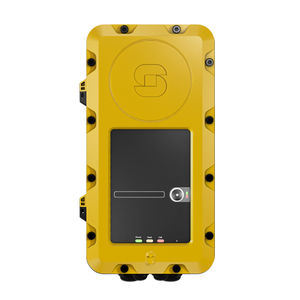
Exigo Industrial Access Panel
- Network access panel for industrial environments
- DSP for acoustic signal processing
- Communication and power over Ethernet
- One programmable button with individual label and status indicators
- Optional button protection cover
- Indicators for power, call and fault
- For single or dual systems (A and B systems)
The EAPII-1 is a rugged access panel, developed for harsh industrial environments. The plastic housing withstands corrosion from the most common corrosive gasses and compounds found in this type of environment.
The access panel features one fully programmable button, which can be used to manually initiate fire alarms, gas alarms or any other action in the Exigo system.
The access panel is equipped with indicators to show the status of the power supply, call activity and whether a fault is present in the system. The access panel’s button features two independent status indicators, which shows the status of the button’s function.
The access panel is fully digital, and connects to the Exigo system over standard Ethernet. Two Ethernet ports are available in order to facilitate redundant cabling and connection to A and B system. The access panel is fully monitored to ensure detection of any fault which may compromise the system’s functionality.
Contents
Installation
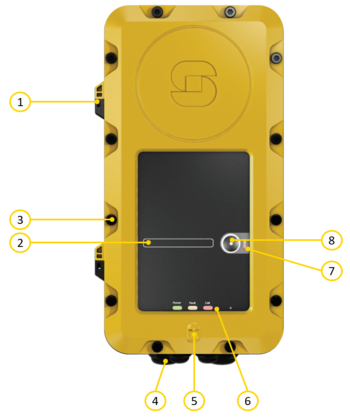
Overview - Front
| 1 | Hinge |
| 2 | Button Label Area |
| 3 | Lid Retention Screw |
| 4 | Cable Glands |
| 5 | Internal Microphone |
| 6 | Status Indicators |
| 7 | Function Indicators |
| 8 | Cover mounting |
| 9 | Function button |
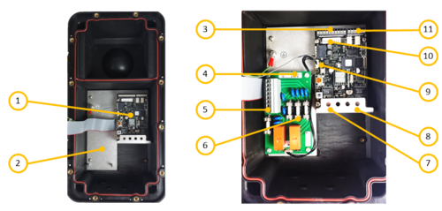
Overview - Internal
| 1 | Processor Board |
| 2 | Mounting for TA-10 |
| 3 | I/O connections |
| 4 | TA-10 Relay Board |
| 5 | Relay Connections |
| 6 | Fuses |
| 7 | Ethernet Port 1 |
| 8 | Ethernet Port 2 |
| 9 | TA-10 Connection |
| 10 | Accessory Interface |
| 11 | Relay Connections |
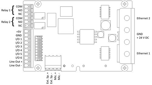
Connections
Restore Factory Defaults
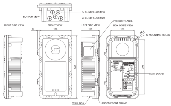
Dimensions
Accessories

|
|
|
|---|---|---|
| EMMAI-2H | TA-10 | TA-23 |
Additional Documentation
For more documentation, please visit the Zenitel web page: https://www.zenitel.com/product/eapii-1
