Difference between revisions of "Turbine to PC physical connection"
(→Modifying the cable) |
(→Connecting the PC to the Turbine device) |
||
| (15 intermediate revisions by the same user not shown) | |||
| Line 1: | Line 1: | ||
This article describes how to make a USB to serial cable. | This article describes how to make a USB to serial cable. | ||
| − | With this cable it is possible to connect direct to Turbine units. This is useful when you have a unit that is bricked. | + | With this cable it is possible to connect a PC direct to Turbine units. This is useful when you have a Turbine unit that is bricked. |
== Preparing the cable for PC-Turbine serial connection == | == Preparing the cable for PC-Turbine serial connection == | ||
| − | To connect the Turbine with the PC we have to modify the serial to USB cable. | + | To connect the Turbine with the PC we have to modify the serial to USB cable. In addition you must also make a strap cable. |
The cable that we will use can be found [http://www.ftdichip.com/Support/Documents/DataSheets/Cables/DS_TTL-232R_CABLES.pdf '''here''']. | The cable that we will use can be found [http://www.ftdichip.com/Support/Documents/DataSheets/Cables/DS_TTL-232R_CABLES.pdf '''here''']. | ||
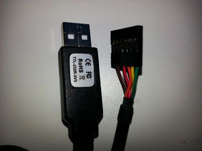
The original cable looks like this: | The original cable looks like this: | ||
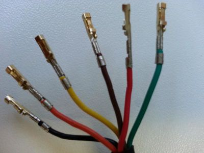
| − | [[File:PC turbine cable 1.jpg|thumb|left| | + | [[File:PC turbine cable 1.jpg|thumb|left|400px|Original USB cable]] |
<br style="clear:both;" /> | <br style="clear:both;" /> | ||
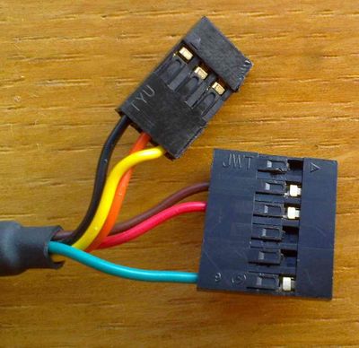
When the modification is done it should look like this: | When the modification is done it should look like this: | ||
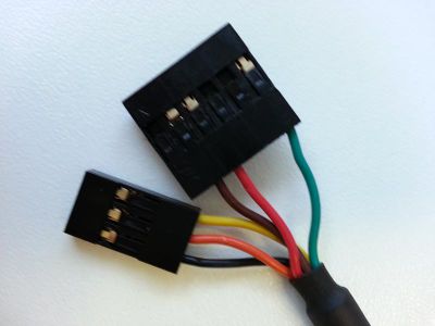
| − | [[File:PC turbine cable 2.jpg|thumb|left| | + | [[File:PC turbine cable 2.jpg|thumb|left|400px|Modified USB cable]] |
<br style="clear:both;" /> | <br style="clear:both;" /> | ||
| Line 19: | Line 19: | ||
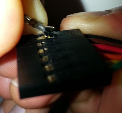
First remove the metal connectors from the plastic casing. This is done by lifting the small plastic clip and then pulling the wire: | First remove the metal connectors from the plastic casing. This is done by lifting the small plastic clip and then pulling the wire: | ||
| − | [[File:PC turbine cable 3.jpg|thumb|left| | + | [[File:PC turbine cable 3.jpg|thumb|left|400px|Remove the metal connectors]] |
<br style="clear:both;" /> | <br style="clear:both;" /> | ||
All the metal connectors must be removed: | All the metal connectors must be removed: | ||
| − | [[File:PC turbine cable 4.jpg|thumb|left| | + | [[File:PC turbine cable 4.jpg|thumb|left|400px|Remove the metal connectors]] |
<br style="clear:both;" /> | <br style="clear:both;" /> | ||
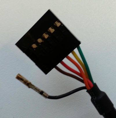
When all the connectors are removed the cable should look like this: | When all the connectors are removed the cable should look like this: | ||
| − | [[File:PC turbine cable 5.jpg|thumb|left| | + | [[File:PC turbine cable 5.jpg|thumb|left|400px|All metal connectors removed]] |
<br style="clear:both;" /> | <br style="clear:both;" /> | ||
| + | When all cables are removed they must be inserted in the new plastic casing. <br> | ||
| + | When this is done the cable should look like this: | ||
| + | [[File:PC turbine cable 6.jpg|thumb|left|400px|The modified cable in the new plastic casing]] | ||
| + | <br style="clear:both;" /> | ||
| + | |||
| + | === Strap Cable === | ||
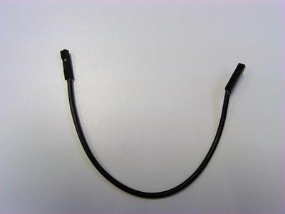
| + | A second cable is also needed witch is used as a strap between Turbine GPIO pinns: | ||
| + | [[File:PC turbine cable 7.jpg|thumb|left|400px|The modified cable in the new plastic casing]] | ||
| + | <br style="clear:both;" /> | ||
| + | |||
| + | That concludes the process of cable creation. You now have a cable kit that makes it possible to connect the PC to a Turbine device. | ||
| + | |||
| + | == Connecting the PC to the Turbine device == | ||
| + | The new cable layout: | ||
| + | {| class="wikitable" | ||
| + | !colspan="6"|3-PIN connector | ||
| + | |- | ||
| + | |BLACK | ||
| + | |GND | ||
| + | |- | ||
| + | |ORANGE | ||
| + | |TXD | ||
| + | |- | ||
| + | |YELLOW | ||
| + | |RXD | ||
| + | |} | ||
| + | |||
| + | {| class="wikitable" | ||
| + | !colspan="6"|6-PIN connector | ||
| + | |- | ||
| + | | | ||
| + | | | ||
| + | |- | ||
| + | |BROWN | ||
| + | |CTS# | ||
| + | |- | ||
| + | |RED | ||
| + | |VCC | ||
| + | |- | ||
| + | | | ||
| + | | | ||
| + | |- | ||
| + | | | ||
| + | | | ||
| + | |- | ||
| + | |GREEN | ||
| + | |RTS# | ||
| + | |} | ||
| + | |||
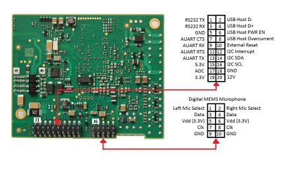
| + | GPIO pinout for the Turbine: | ||
| + | [[File:PC turbine cable 8.jpg|thumb|left|400px|GPIO pinout for the Turbine device]] | ||
| + | <br style="clear:both;" /> | ||
| + | |||
| + | Connecting the cable: | ||
| + | [[File:PC turbine cable 9.jpg|thumb|left|400px|Connecting the cable to the Turbine device]] | ||
| + | <br style="clear:both;" /> | ||
| + | [[File:PC turbine cable 10.jpg|thumb|left|400px|Connecting the cable to the Turbine device]] | ||
| + | <br style="clear:both;" /> | ||
| + | === Connecting the strap cable === | ||
| + | The strap cable needs to be connected like this: | ||
| + | |||
| + | [[File:PC turbine cable 11.jpg|thumb|left|400px|Strap cable connection]] | ||
| + | <br style="clear:both;" /> | ||
| + | |||
| + | [[File:PC turbine cable 12.jpg|thumb|left|400px|Strap cable connection]] | ||
| + | <br style="clear:both;" /> | ||
| + | |||
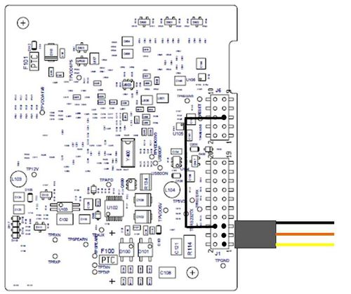
| + | == The PC Turbine cable connection overview == | ||
| + | This is the overview of the connetion between the PC and the Turbine device: | ||
| + | |||
| + | [[File:PC turbine cable 13.jpg|thumb|left|500px|PC Turbine connection overview]] | ||
| + | <br style="clear:both;" /> | ||
[[Category:Troubleshooting]] | [[Category:Troubleshooting]] | ||
Latest revision as of 10:51, 8 May 2018
This article describes how to make a USB to serial cable. With this cable it is possible to connect a PC direct to Turbine units. This is useful when you have a Turbine unit that is bricked.
Contents
Preparing the cable for PC-Turbine serial connection
To connect the Turbine with the PC we have to modify the serial to USB cable. In addition you must also make a strap cable.
The cable that we will use can be found here.
The original cable looks like this:
When the modification is done it should look like this:
Modifying the cable
There is no soldering or crimping required for this process.
First remove the metal connectors from the plastic casing. This is done by lifting the small plastic clip and then pulling the wire:
All the metal connectors must be removed:
When all the connectors are removed the cable should look like this:
When all cables are removed they must be inserted in the new plastic casing.
When this is done the cable should look like this:
Strap Cable
A second cable is also needed witch is used as a strap between Turbine GPIO pinns:
That concludes the process of cable creation. You now have a cable kit that makes it possible to connect the PC to a Turbine device.
Connecting the PC to the Turbine device
The new cable layout:
| 3-PIN connector | |||||
|---|---|---|---|---|---|
| BLACK | GND | ||||
| ORANGE | TXD | ||||
| YELLOW | RXD | ||||
| 6-PIN connector | |||||
|---|---|---|---|---|---|
| BROWN | CTS# | ||||
| RED | VCC | ||||
| GREEN | RTS# | ||||
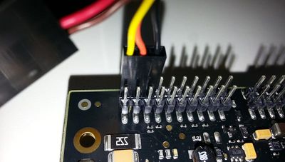
GPIO pinout for the Turbine:
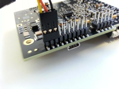
Connecting the cable:
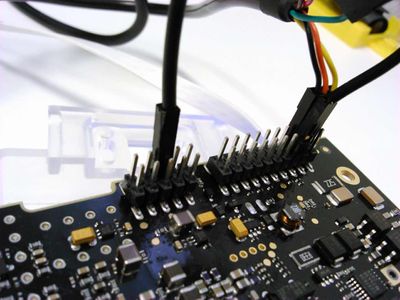
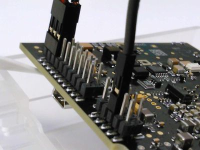
Connecting the strap cable
The strap cable needs to be connected like this:
The PC Turbine cable connection overview
This is the overview of the connetion between the PC and the Turbine device:
