Difference between revisions of "EPIPR-6"
(→Overview - Back) |
|||
| (14 intermediate revisions by 2 users not shown) | |||
| Line 1: | Line 1: | ||
| − | [[File:EPIPR-6. | + | [[File:EPIPR-6 Front.PNG|thumb|alt=EPIPR-6.|EPIPR-6]] |
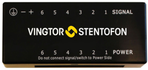
'''Exigo Power Injector, Spare Pair PoE, 6 Ports''' | '''Exigo Power Injector, Spare Pair PoE, 6 Ports''' | ||
| − | == Additional | + | == Installation == |
| + | ===Overview - Front=== | ||
| + | [[File:EPIPR-6 Overview.PNG|left|500px]] | ||
| + | <br style="clear:both;" /> | ||
| + | {| border="1" | ||
| + | | align="center" style="background:#ffd400;" width="50pt"| 1 || align="left" | Output ports || align="left"| Ethernet ports carrying data and power | ||
| + | |- | ||
| + | | align="center" style="background:#ffd400;" width="50pt"| 2 || align="left" | Power switch || align="left"| Power switch to individually turn on/off spare pair PoE on the output ports | ||
| + | |- | ||
| + | | align="center" style="background:#ffd400;" width="50pt"| 3 || align="left" | Fuses || align="left"| Replaceable fuse for each output port | ||
| + | |- | ||
| + | | align="center" style="background:#ffd400;" width="50pt"| 4 || align="left" | DIN mounting clip || align="left"| Plastic clip to mount the EPIPR-6 unit to a DIN rail | ||
| + | |- | ||
| + | | align="center" style="background:#ffd400;" width="50pt"| 5 || align="left" | Lid retention clip || align="left"| Small plastic clip which must be depressed to remove the top cover | ||
| + | |- | ||
| + | |} | ||
| + | <br> | ||
| + | ----------- | ||
| + | |||
| + | ===Overview - Back=== | ||
| + | [[File:Epipr 6 back connection.PNG|left|400px]] | ||
| + | <br style="clear:both;" /> | ||
| + | {| border="1" | ||
| + | | align="center" style="background:#ffd400;" width="50pt"| 1 || align="left" | Input ports || align="left"| Ethernet port for connection to the central switch | ||
| + | |- | ||
| + | | align="center" style="background:#ffd400;" width="50pt"| 2 || align="left" | Mounting clip || align="left"| Plastic clip to mount the EPIPR-6 unit to a DIN rail | ||
| + | |- | ||
| + | | align="center" style="background:#ffd400;" width="50pt"| 2 || align="left" | Power input || align="left"| Power connection for power to the PoE devices | ||
| + | |- | ||
| + | |} | ||
| + | <br> | ||
| + | ----------- | ||
| + | |||
| + | ===Placement=== | ||
| + | When used in an equipment rack, the EPIPR-6 can be mounted at any accessible location. | ||
| + | |||
| + | ===Mounting=== | ||
| + | The EPIPR-6 is a DIN-rail mounted device, and hence requires a DIN rail. The DIN rail shall be mounted securely to the equipment rack, and properly stabilized. The DIN clips on the EPIPR-6 | ||
| + | shall be properly secured to the DIN rail. | ||
| + | |||
| + | ===Power Supply=== | ||
| + | The EPIPR-6 unit itself requires no power to operate. The voltage supplied to the unit is only inserted on the spare pairs of the Cat cable. The voltage required by the PoE standard is 48 VDC, | ||
| + | and hence the Exigo access panels require the same 48 VDC. | ||
| + | |||
| + | The 48 VDC to the EPIPR-6 unit can either be supplied by the same power as the network switch, or by separate power supplies. The power supply feeding the EPIPR-6 must be duplicated, i.e. connected to the equipment rack’s primary and secondary power supplies in the case of a single system. In the case of an A-B system, the access panels will be supplied by one EPIPR-6 unit in each equipment rack, maintaining the requirement for power redundancy. | ||
| + | |||
| + | ===Ethernet Connections=== | ||
| + | The Ethernet connections from the input ports shall be routed to the central switch in the equipment rack using UTP Cat5 cables or better. The output Ethernet connections shall be routed | ||
| + | to RJ45 terminal blocks or patch panels in the equipment rack. | ||
| + | |||
| + | {{Warn}} | ||
| + | '''''Do not connect the outputs of the EPIPR-6 to equipment other than spare pair PoE''''' | ||
| + | '''''enabled field equipment as this may damage the equipment if the Ethernet is not ''''' | ||
| + | '''''properly terminated internally. If the output must be connected to such equipment,''''' | ||
| + | '''''make sure to disable the spare pair PoE by turning the switch internally in the''''' | ||
| + | '''''EPIPR-6.''''' | ||
| + | |||
| + | == Dimensions == | ||
| + | [[File:EPIPR-6 Dimensions.PNG]] | ||
| + | <br style="clear:both;" /> | ||
| + | |||
| + | == Additional Documentation == | ||
For more documentation, please visit the Zenitel web page: https://www.zenitel.com/product/epipr-6 | For more documentation, please visit the Zenitel web page: https://www.zenitel.com/product/epipr-6 | ||
[[Category:Hardware]] | [[Category:Hardware]] | ||
Latest revision as of 12:26, 4 May 2018
Exigo Power Injector, Spare Pair PoE, 6 Ports
Contents
Installation
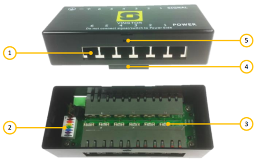
Overview - Front
| 1 | Output ports | Ethernet ports carrying data and power |
| 2 | Power switch | Power switch to individually turn on/off spare pair PoE on the output ports |
| 3 | Fuses | Replaceable fuse for each output port |
| 4 | DIN mounting clip | Plastic clip to mount the EPIPR-6 unit to a DIN rail |
| 5 | Lid retention clip | Small plastic clip which must be depressed to remove the top cover |
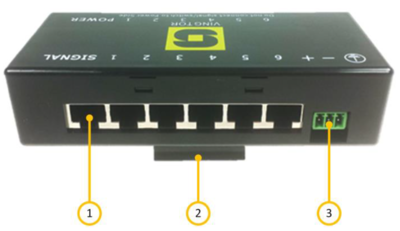
Overview - Back
| 1 | Input ports | Ethernet port for connection to the central switch |
| 2 | Mounting clip | Plastic clip to mount the EPIPR-6 unit to a DIN rail |
| 2 | Power input | Power connection for power to the PoE devices |
Placement
When used in an equipment rack, the EPIPR-6 can be mounted at any accessible location.
Mounting
The EPIPR-6 is a DIN-rail mounted device, and hence requires a DIN rail. The DIN rail shall be mounted securely to the equipment rack, and properly stabilized. The DIN clips on the EPIPR-6 shall be properly secured to the DIN rail.
Power Supply
The EPIPR-6 unit itself requires no power to operate. The voltage supplied to the unit is only inserted on the spare pairs of the Cat cable. The voltage required by the PoE standard is 48 VDC, and hence the Exigo access panels require the same 48 VDC.
The 48 VDC to the EPIPR-6 unit can either be supplied by the same power as the network switch, or by separate power supplies. The power supply feeding the EPIPR-6 must be duplicated, i.e. connected to the equipment rack’s primary and secondary power supplies in the case of a single system. In the case of an A-B system, the access panels will be supplied by one EPIPR-6 unit in each equipment rack, maintaining the requirement for power redundancy.
Ethernet Connections
The Ethernet connections from the input ports shall be routed to the central switch in the equipment rack using UTP Cat5 cables or better. The output Ethernet connections shall be routed to RJ45 terminal blocks or patch panels in the equipment rack.
Do not connect the outputs of the EPIPR-6 to equipment other than spare pair PoE
enabled field equipment as this may damage the equipment if the Ethernet is not
properly terminated internally. If the output must be connected to such equipment,
make sure to disable the spare pair PoE by turning the switch internally in the
EPIPR-6.
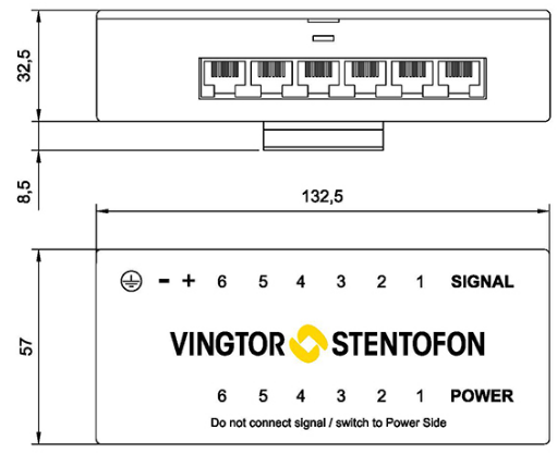
Dimensions
Additional Documentation
For more documentation, please visit the Zenitel web page: https://www.zenitel.com/product/epipr-6


